FireSwitch108 - 7 -
Terminal Identification Table:
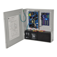
Power Supply Board
Terminal Legend Function/Description
L, G, N
Connect 120VAC to these terminals: L to Hot, N to Neutral.
Earth Ground should be connected via grounding lug.
+ DC – 24VDC non power- limited output.
AC FAIL
(delayed)
NO, C, NC
Form “C” dry contacts indicate the loss of AC, with AC present terminals marked [NO] and
[C] are open, [NC] and [C] are closed. When loss of AC occurs terminals marked [NO]
and [C] are closed, [NC] and [C] are open.
AC LOCAL
(instant)
NO, C, NC
Form “C” dry contacts used to instantaneously signal the loss AC to local annunciation
devices, with AC present terminals marked [NO and C] are open, [NC and C] are closed.
When loss of AC occurs terminals marked [NO and C] are closed, [NC and C] are open.
BAT FAIL
NO, C, NC
Form “C” dry contacts indicate low battery voltage or loss of battery voltage.
Under normal conditions terminals marked [NO and C] are open, [NC and C] are closed.
During a trouble condition terminals marked [NO and C] are closed, and [NC and C] are open
(Fig. 2, pg. 5).
– BAT +
Stand-by battery input (leads provided). Maximum charging voltage is 26.4VDC,
maximum charging current is 1.5A (Fig. 2, pg. 5).
*Power Supply Board Parameter Specifications:
NOTICE TO USERS, INSTALLERS, AUTHORITIES HAVING JURISDICTION, AND OTHER INVOLVED PARTIES
This product is field-configurable. In order for the product to comply with the requirements in the Standard for Control
Units and Accessories for Fire Alarm System (UL 864), set programming features as indicated below.
Program feature or option Permitted in UL 864? (Y/N) Possible Settings Settings Permitted in UL 864
AC Reporting Delay Yes 2 hours or 1 minute 1 hour to 3 hours
AC Trouble Reporting
to host panel
Yes enable/disable enable
BAT Trouble Reporting
to host panel
Yes enable/disable enable
• To set AC Delay for 2 hours or 1 minute - power the unit down
(AC supply and Battery) prior to changing switch position -
Turn switch “AC Delay” ON or OFF, respectively (Fig. 3, pg. 7).
• Factory setting is 2 hours - for testing purposes change to 1 minute
by turning AC Delay switch ON temporarily.
• Low battery condition will report at approximately 20VDC.
• Battery presence detection will report within 100 seconds after
battery remains undetected (missing or removed).
A restored battery will report within 30 seconds.
LED Diagnostics:
Power Supply Board
Red (DC) Green (AC) Power Supply Status
ON ON Normal operating condition.
ON OFF Loss of AC. Stand-by batteries are supplying power.
OFF ON No DC output.
OFF OFF Loss of AC. Discharged or no stand-by battery. No DC output.
ON
OFF - 2 Hours
ON - 1 Minute
Switch Detail
Fig. 3