FireSwitch108 - 9 -
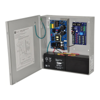
Connection Diagram:
Fig. 5
Magnetic
Door
Holder
Digital
Communicator
or Local
Annunciator
Dry output Contact
(Form "C" contacts)
Addressable
control module
trigger output
24VDC
Regulated
Power-Limited
Non Supervised,
Class E
Output
Factory Installed
Board Interface
Cable to
Power Supply
Ethernet
Power-Limited
Power-
Limited
Fire
Alarm
Control
Panel
(FACP)
Special Application Output selected as Aux. Output
Compatible Special Application Devices
Refer to Appendix B for
Compatible Devices, pg. 20 - 23
INP1 RET1 INP2 RET2 OUT1 OUT2 OUT3 OUT4 OUT5 OUT6 OUT7 OUT8
+ SYNC --- GF1 GF2 NC NO C EARTH
NEGATIVE
POSITIVE
INP2
INP1
INP2
INP1
ETHERNET
ON
RIGHTLEFT
UP
DOWN
PRESS DOWN
FOR ENTER
+ 24V -- + AUX --
Programming:
To begin programming depress and hold down the joystick (approximately 2 secs.).
Note: If FireSwitch remains dormant for more than 90 seconds, it will return to stand-by status screen.
Step 1. Setup Outputs 1-8:
a. Select from: Class A, Class B or Aux. Outputs with or without battery backup (see chart below).
Output Configuration:
LCD Legend Function/Description
A Class A output (Combines two (2) outputs, ex. 1-2, 3-4, 5-6, 7-8).
B Class B output.
Ax Aux. output with battery backup.
Bx Aux. output without battery backup.
b. Depress the joystick one time from Stand-by screen.
c. Use [Up/Down] to select Function, Use [Left/Right] to select channel.