FireSwitch108 - 19 -
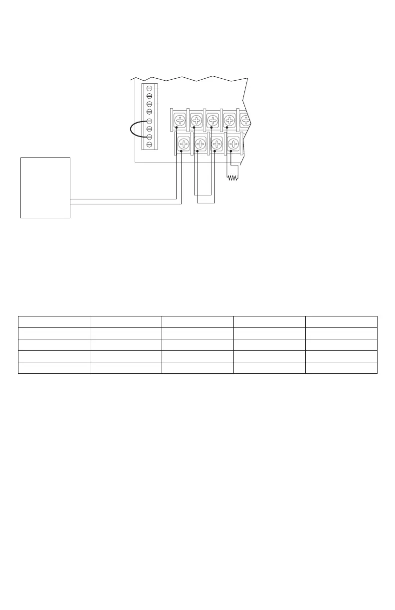
8. Using a Single FACP Output:
When only one FACP output is available, you may connect both Input1 and Input2 to it.
Wire [RET1+] and [RET1–] to [INP2+] and [INP2–].
Both visual and audible notification appliances will be activated simultaneously (Fig. 13, pg. 19).
Fig. 13
Dip Switches 1-4 Settings:
Dry contact INP1 configuration set SW1 and SW3 to the ON position.
Dry contact INP2 configuration set SW2 and SW4 to the ON position.
When connecting INP1 to the sync output of FireSwitch unit for synchronization purposes set SW1 to the ON
position and SW3 to the OFF position. For INP2 to the sync output of FireSwitch unit for synchronization pur-
poses set SW2 to the ON position and SW4 to the OFF position.
SW1 SW2 SW3 SW4
INP1 - Dry NC ON – ON –
INP2 - Dry NC – ON – ON
INP1 - Sync ON – OFF –
INP2 - Sync – ON – OFF
Control Circuit
No Notification Appliances Allowed
INP1 RET1 INP2 RET2
NEGATIVE
POSITIVE
To INP1
FACP
(Fire Alarm
Control Panel)
10K EOL or Next Device.
For Class A configuration
connect RET2 to FACP
+ SYNC --- NC GND NC NO C EARTH