II-12
Checking electrical connections
W
hen the necessary electrical connections are completed, check that
they are correctly made as described below. For the description of the
switches, buttons and lights, refer to Part III, Controls.
1 Close and screw the door of the electrical enclosure.
2 Turn on the shop circuit breaker switch, and turn the POWER
switch on the electrical enclosure to ON to illuminate the POWER
ON light on the control panel.
3 Press and illuminate the HYDRAULIC ON button on the control
panel to start the hydraulic pump motor.
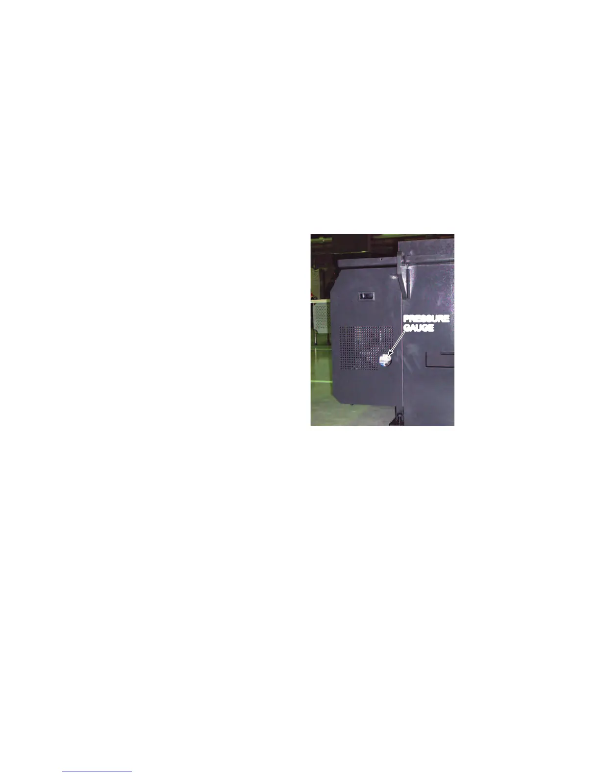
4 If the pressure gauge
reads the set
pressure of 3.5 MPa
{508 psi}, go to step
11.
If the pressure gauge
does not read the set
pressure of 3.5 MPa
{508 psi}, immediately
press the
HYDRAULIC OFF
button on the control
panel, and go to step
5.
PRESSURE
GAUGE
5 Turn the POWER switch to OFF, and turn off the shop circuit
breaker switch.
6 Unscrew and open the door of the electrical enclosure, and
interchange two of the three power cable conductors.
7 Close and screw the door of the electrical enclosure.
8 Turn on the shop circuit breaker switch, and turn the POWER
switch to ON.
9 Press and illuminate the HYDRAULIC ON button.
10 Check again that the pressure gauge reads the set pressure of 3.5
MPa {508 psi}.
11 Press the HYDRAULIC OFF button to stop the hydraulic pump
motor.
12 Turn the POWER switch to OFF, and turn off the shop circuit
breaker switch.