ELECTRICAL SHOCK HAZARD
– Turn off power at the main service panel by removing
the fuse or switching the appropriate circuit breaker to the OFF position before
removing the existing thermostat.
1. Turnoffpowertotheheatingandcoolingsystembyremovingthefuseorswitchingthe
appropriatecircuitbreakeroff.
2. Removecoverofoldthermostat.Thisshouldexposethewires.
3. Labeltheexistingwireswiththeenclosedwirelabelsbeforeremovingwires.
4. Afterlabelingwires,removewiresfromwireterminals.
5. Removeexistingthermostatbasefromwall.
6. Refertothefollowingsectionforinstructionsonhowtoinstallthisthermostat.
To Remove Existing Thermostat
Specifications
Electrical rating: •24VAC(18-30VAC)
•4ampmaximumtotalload
•1ampmaximumperterminal
Temperature control range: 45°Fto90°F(7°Cto32°C)Accuracy:±1°F(±0.5°C)
System congurations:2-stageheat&1-stagecoolheatpump,1-stageelectricheat
Timing:
Anti-shortCycle:
4minutes
BacklightOperation:10seconds
Terminations:R,C,O/B,Y,W,GH,GL
Important Safety Information
WARNING!
:
Always turn off power at the main power supply before installing, cleaning,
or removing thermostat.
•Thisthermostatisfor24VACapplicationsonly;donotuseonvoltagesover30VAC
•Allwiringmustconformtolocalandnationalelectricalandbuildingcodes
•Donotuseairconditioningwhentheoutdoortemperatureisbelow50degrees;thiscandamage
yourA/Csystemandcausepersonalinjuries
•Usethisthermostatonlyasdescribedinthismanual
Package Contents/Tools Required
Package includes: Amana
®
2246003thermostatonbase,thermostatcover,wiringlabels,screws
andwallanchors,Installation,OperationandApplicationGuide
Tools required for installation:Drillwith3/16”bit,hammer,screwdriver
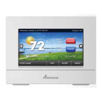
Installation, Operation &
Application Guide
www.amana-ptac.com
2246003
Non-Programmable Electronic Thermostat
Electric Heat or HP, Manual Changeover, Hardwired
• Congurable
• 2-Stage Heat Pump Systems
• 1-Stage Electric Heat
• Backlit Display
• Field Calibration Feature
• Relay Outputs
(minimum voltage drop in thermostat)
• Ideally Suited for:
–Residential(NewConstruction/Replacement)
–LightCommercial
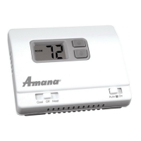
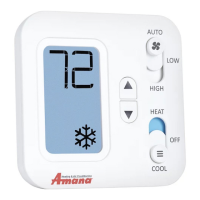
Parts Diagram
RESET
LEFT RIGHT
FanSwitchModeSwitch
Left
Button
Right
Button
ResetSwitch
LargeBacklitDisplay
UpButton
DownButton
ELECTRICAL SHOCK HAZARD
– Turn off power at the main service panel by removing
the fuse or switching the appropriate circuit breaker to the OFF position before
removing the existing thermostat.
IMPORTANT: Thermostatinstallationmustconformtolocalandnationalbuildingand
electricalcodesandordinances.
Note:Mount the thermostat about four feet above the oor. Do not mount the thermostat
on an outside wall, in direct sunlight, behind a door, or in an area affected by a vent
or duct.
1.Turnoffpowertotheheatingandcoolingsystembyremovingthefuseorswitchingtheappropriate
circuitbreakeroff.
2. Toremovecover,insertandtwistacoinorscrewdriverintheslotsontopofthethermostat.
3. Putthermostatbaseagainstthewallwhereyouplantomountit(Besurewireswillfeedthrough
thewireopeninginthebaseofthethermostat).
4. Marktheplacementofthemountingholes.
5. Setthermostatbaseandcoverawayfromworkingarea.
6. Usinga3/16”drillbit,drillholesintheplacesyouhavemarkedformounting.
7. Useahammertotapsuppliedanchorsinmountingholes.
8. Alignthermostatbasewithmountingholesandfeedthecontrolwiresthroughwireopening.
9. Usesuppliedscrewstomountthermostatbasetowall.
10.Insertstripped,labeledwiresinmatchingwireterminals.See“WiringDiagrams”sectionofthis
manual.
CAUTION!
:
Besureexposedportionofwiresdoesnottouchotherwires.
11. Gentlytugwiretobesureofproperconnection.Doublecheckthateachwireisconnectedtothe
properterminal.
12.Sealholeforwiresbehindthermostatwithnon-ammableinsulationorputty.
13.Replacecoveronthermostatbysnappingitinplace.
14.Turnonpowertothesystematthemainservicepanel.
15.Testthermostatoperationasdescribedin“TestingtheThermostat”.
To Install Thermostat
Terminal Designator Descriptions
R – 24VAChot
C – 24VACcommon
O/B – Reversingvalve
Y – 1ststagecool,1ststageHPheatforHP
W – 2ndstageheatforHP,1ststageelectricheat
GH – FanHigh
GL – FanLow
Wiring Diagram Conversions
Cool & Electric Heat Heat Pump
Output Chart
1
ST
Cool 1
ST
Heat 2
ND
Heat
HSo=HeatPump(coolactivereversingvalve)
Y,GL,O Y,GL Y,GL,W
HSb=HeatPump(heatactivereversingvalve)
Y,GL Y,GL,B Y,GL,B,W
HSE=ElectricHeat
Y,GL W,GL W,GL
Note:GL will be on during heating and cooling cycle when fan switch is set to Auto
FanHigh
FanLow
Heat
Compressor
X
Former
ReversingValve
AuxiliaryHeat
Compressor
FanHigh
FanLow
X
Former