Do you have a question about the Amana PHWT-A200 and is the answer not in the manual?
Wiring connections for Heat Pump PTAC units, including notes on terminal usage.
Wiring connections for Conventional PTAC units, with specific notes for system type and electric heat.
Steps to enter the installer settings menu by cycling through system modes.
Instructions for activating and deactivating Emergency Heat mode on compatible Heat Pump units.
How to enable or disable the keypad lockout to prevent user changes.
The Amana PHWT-A200 is a programmable electronic thermostat designed for controlling heating and cooling systems in various applications, including conventional PTAC (Packaged Terminal Air Conditioner) units and heat pump PTAC units, both with or without electric heat. This thermostat is intended for low voltage applications only, emphasizing safety and compliance with electrical codes.
Before installation, it is crucial to turn off electricity to all heating and cooling components. When removing an existing thermostat, users should carefully note the wiring connections, including the letters near each terminal and the color of the connected wires. Self-adhesive wire labels are provided to assist with this process. Wires should be handled carefully to prevent them from falling back into the wall or touching each other. The existing thermostat base must then be removed from the wall.
For installing the new thermostat, it should be mounted on an inside wall, approximately five feet above the floor, in an area with good air circulation but not directly affected by a vent or duct. If painting or construction is ongoing, the thermostat should be covered or installation should wait until the work is complete. If new mounting holes are required, their placement should be marked through the thermostat base. A 3/16" drill bit is used to drill these holes, and the supplied wall anchors should be inserted. Wires are fed through the wire opening in the base, and the base is mounted to the wall using the provided screws. Wiring involves connecting each terminal on the new thermostat base according to the wiring diagrams provided in the manual. It is essential to ensure that the bare end of each wire is fully seated into the connector and tightened securely. A gentle pull on the wires confirms their secure connection. After wiring, the thermostat front is placed back onto the base. Power is then restored to the heating and cooling components and the thermostat. Finally, the installer settings menu is accessed to adjust the required settings for the specific system type.
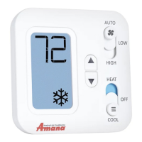
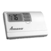
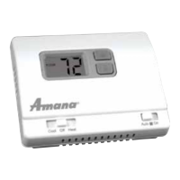
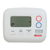
The thermostat features a user-friendly front panel with distinct buttons for system mode and fan mode, along with Up and Down buttons for temperature adjustment and setting selection. The System Mode button allows users to cycle through available modes: AUTO, OFF, HEAT, and COOL. AUTO mode automatically selects heat/cool as needed, though this can be disabled in installer settings. OFF mode stops all heating or cooling functions. HEAT mode permits heating operation, and COOL mode permits cooling operation. The desired mode is underlined, and after two seconds without a button press, the underlined mode is entered.
The Fan Mode button allows selection of fan operation: FAN AUTO, FAN LOW, or FAN HIGH. FAN AUTO operates the fan in low or high speed only when there is a call for heating or cooling. FAN LOW runs the fan continuously at low speed, with heating or cooling components cycling on and off as needed. FAN HIGH runs the fan continuously at high speed, with heating or cooling components cycling on and off as needed. Similar to system mode, the desired fan mode is underlined and entered after two seconds of inactivity.
The Up and Down buttons are primarily used to raise or lower the target set temperature and to select user options and settings on the display. The temperature displayed in normal operation is always the target set temperature. To view the current ambient room temperature in Auto, Heat, or Cool mode, both the Up and Down buttons can be pressed simultaneously. When adjusting the target set temperature, the thermostat must be in Auto, Heat, or Cool mode. Presses to the Up or Down buttons have no effect when the thermostat is in Off mode.
The thermostat includes an installer settings menu for advanced configuration. To enter this menu, the thermostat must be powered, and the System Mode button pressed until OFF is underlined. After OFF mode is confirmed, both the Up and Down buttons are pressed and held for at least five seconds until the screen changes. To change an entry within the menu, the Up or Down buttons are used to select the desired setting option. To advance to the next menu item, the Mode button is pressed once. To exit the installer settings menu and return to the main thermostat screen, the System Mode button is pressed one more time while at the last menu item. The system automatically exits the installer settings menu after one minute of no button presses, saving all items as they were last shown.
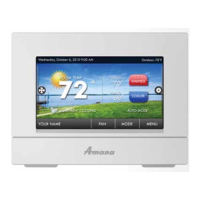
The thermostat supports automatic daylight savings time adjustment by default, which can be disabled in the installer menu. It also allows for setting the clock and temperature program schedule. To access this, with the thermostat powered, the System Mode button is pressed until OFF is underlined. After OFF mode is confirmed, both the Menu and Up buttons are pressed and held for at least five seconds until the screen changes. Within this menu, the Up or Down buttons move the underline to the selection item, and the System Mode button is pressed once to enter the selection. Options include adjusting the real-time clock (CLOCK DIGITS), heating temperature set points (HEAT), cooling temperature set points (COOL), and exiting the menu (EXIT?).
Adjusting the real-time clock involves using the Up or Down buttons to adjust the blinking hour digits, cycling through AM and PM. The Menu button is then pressed to advance to minutes, year, month, and day, each adjusted with the Up/Down buttons.
For programming heat or cool temperature schedules, each period ends at the start time of the next upcoming period. If configured for two periods, only DAY and NIGHT are used. For one period and seven-day programming, the thermostat resets to the desired set temperature daily. Upon entering heating or cooling programming sections, users select which day(s) to adjust with the same settings (e.g., all weekdays or each day separately). The Up/Down buttons scroll through blinking days, and the Menu button selects each day with an underline. Once days are selected, the blinking selection moves to PROG?, and the Menu button is pressed to proceed. The start time of the first program period is adjusted using Up/Down buttons, and the Menu button advances. This step-by-step process is repeated for all remaining periods. After all periods are adjusted, the screen blinks EXIT?. If more days need adjustment, Up/Down selects other days. If done, the Menu button exits the programming menu. These steps apply only to the mode just programmed; the process must be repeated for the alternative mode if necessary. Once all setting changes are complete, moving the underline to EXIT? and pressing the Menu button returns to the main home screen.
For heat pump units, an Emergency Heat Mode can be entered. In regular HEAT mode, both the Mode and Fan buttons are pressed and held for at least five seconds until the screen changes. The thermostat displays HEAT with "E" to confirm Emergency Heat mode, using only the W2 wire terminal for heating and bypassing compressor heating. To return to normal heating mode, both buttons are pressed and held again for at least five seconds. The "E" disappears, and only "HEAT" is shown.
A keypad/front panel lockout feature is available to prevent unauthorized changes. In any normal operating mode except OFF, a lockout can be activated, preventing mode, fan, or temperature adjustments. When locked, any button press illuminates the display backlight. To activate or deactivate the lockout, both the MODE and FAN buttons are pressed and held for at least five seconds. A padlock icon appears in the lower left corner of the display when locked.
The thermostat also includes a compressor protection bypass, which is a contractor/installer mode that temporarily turns off compressor delays for system testing, automatically returning to normal operation after five minutes. A full reset option is available to return all settings to factory defaults.
| Stages | 1 Heat/1 Cool |
|---|---|
| Programming | 7-day programmable |
| Hold Function | Yes |
| Filter Change Alert | Yes |
| Battery Backup | Yes |
| Type | Programmable |
| Voltage | 24V |
| Display | Digital |