Terminals S1 and S2 can be used for an indoor remote sensor.
The indoor remote sensor is used to read the indoor temperature
in a different location. This is benecial when the thermostat is not
mounted in the ideal location.
1. Remove cover from remote sensor housing.
2. Select an appropriate location for mounting the remote sensor.
3. Mount remote sensor unit using hardware provided.
4. Install two strand shielded wire between remote sensor and
thermostat. Shielded wire is recommended.
Do not run remote sensor wire in conduit with other wires.
• Wire 1 should run between the S1 terminal on the thermostat
and the S1 terminal on the remote sensor
• Wire 2 should run between the S2 terminal on the thermostat
and the S2 terminal on the remote sensor
• Connect the shielding of the wire to the S2 terminal on the thermostat
5. Congure the thermostat to operate with the remote indoor sensor (see Conguration Mode setting 13).
Remote Sensor Installation (Optional)
Note: Remoteoroutdoorsensorreadingcanbe
displayedbysimultaneouslypressingthe
DownandSYSbuttons.
Remote Sensor:
(Shown:OptionalICMACC-RT103RemoteIndoor
Sensor;foroutdoorsensor,orderACC-OD103.)
Specifications
Electrical rating: • 24 VAC (18-30 VAC)
• 1 amp maximum per terminal
• 3 amp maximum total load
Temperature control range: 45°F to 90°F (7°C to 32°C) Accuracy: ± 1°F (± 0.5°C)
System congurations: 2-stage heat, 2-stage cool, heat pump, gas, oil, electric
Timing: Anti-short Cycle: 4 minutes (bypass anti-short cycle delay by returning to OFF mode for 5 seconds)
Backlight Operation: 10 seconds
Terminations: S1, S2, R, C, W/O/B, Y1, W2, Y2, G
Package Contents/Tools Required
Package includes: Amana
®
2246008 thermostat on base, thermostat cover, wiring labels, screws and wall
anchors, Installation, Operation and Application Guide
Tools required for installation: Drill with 3/16” bit, hammer, screwdriver
Important Safety Information
WARNING!
:
Always turn off power at the main power supply before installing, cleaning, or removing
thermostat.
• This thermostat is for 24 VAC applications only; do not use on voltages over 30 VAC
• Do not short across terminals of gas valve or system control to test operation; this will damage your thermostat
and void your warranty
• All wiring must conform to local and national electrical and building codes
• Do not use air conditioning when the outdoor temperature is below 50 degrees; this can damage your A/C system
and cause personal injuries
• Use this thermostat only as described in this manual
To Remove Existing Thermostat
ELECTRICAL SHOCK HAZARD
– Turn off power at the main service panel by removing the fuse
or switching the appropriate circuit breaker to the OFF position before removing the existing
thermostat.
1. Turn off power to the heating and cooling system by removing the fuse or switching the appropriate circuit
breaker off.
2. Remove cover of old thermostat. This should expose the wires.
3. Label the existing wires with the enclosed wire labels before removing wires.
4. After labeling wires, remove wires from wire terminals.
5. Remove existing thermostat base from wall.
6. Refer to the following section for instructions on how to install this thermostat.
To Install Thermostat
ELECTRICAL SHOCK HAZARD
– Turn off power at the main service panel by removing the fuse
or switching the appropriate circuit breaker to the OFF position before removing the existing
thermostat.
IMPORTANT: Thermostatinstallationmustconformtolocalandnationalbuildingandelectricalcodesand
ordinances.
Note: Mountthethermostataboutvefeetabovetheoor.Donotmountthethermostatonanoutsidewall,in
directsunlight,behindadoor,orinanareaaffectedbyaventorduct.
1. Turn off power to the heating and cooling system by removing the fuse or switching the appropriate circuit breaker
off.
2. To remove cover, pull gently at the seam at the top.
3. Put thermostat base against the wall where you plan to mount it (Be sure wires will feed through the wire opening
in the base of the thermostat).
4. Mark the placement of the mounting holes.
5. Set thermostat base and cover away from working area.
6. Using a 3/16” drill bit, drill holes in the places you have marked for mounting.
7. Use a hammer to tap supplied anchors in mounting holes.
8. Align thermostat base with mounting holes and feed the control wires through slit in thermal intrusion barrier and
into wire opening.
9. Use supplied screws to mount thermostat base to wall.
10. Insert stripped, labeled wires in matching wire terminals.
CAUTION!
: Besureexposedportionofwiresdoesnottouchotherwires.
11. Gently tug wire to be sure of proper connection. Double check that each wire is connected to the proper
terminal.
12. Turn on power to the system at the main service panel.
13. Congure thermostat to match the type of system you have.
14. Replace cover on thermostat by snapping it in place.
15. Test thermostat operation as described in “Testing the Thermostat”.
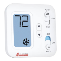
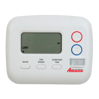
Parts Diagram
Conguration
switch
Reset switch
Left (system) button
Right (fan) button
Down button
Up button
Icon Descriptions
Cooling operation icon
Fan operation icon
Heating operation icon
Lock mode activated
Room temperature
offset activated
S1 S2 R C W
O/B
GY1 W2 Y2
RESET CONFIG
Terminal Designator Descriptions
1
ST
Cool 2
ND
Cool 1
ST
Heat 2
ND
Heat
Heat/Cool Y1,G YI,Y2,G W1,G* W1,W2,G*
Heat Pump (One Compressor) Y1,G,O Y1,G,O Y1,G,B Y1,W2,G,B
Heat Pump (Two Compressors) Y1,G,O Y1,Y2,G,O Y1,G,B Y1,Y2,G,B
Electric Heat (Heat Pump Only) N/A N/A W2,G W2,G
* G not energized when congured as a gas/oil system
The Amana
®
2246008 thermostat is congurable for all systems. The conguration directly affects the outputs.
Use the output chart to correctly congure and wire the thermostat to your system.
Amana® 2246008 Output Chart
Configuration Mode
OFF
PM
1. Verify the Amana
®
2246008 is in the OFF mode.
Press the SYS (left) button until off mode displays.
2. Remove the cover of the thermostat by gently pulling near one of the corners at
the top of the thermostat.
3. Press the CONFIG button for 1 second while the Amana
®
2246008 is in OFF
mode.
To exit conguration mode, press the CONFIG switch for 1 second.
Press the up or down button to change settings within each screen.
Down button
Up button
Press the right button to advance to the next screen.
Note: Pressingthe
left
buttonwillreturnyoutothepreviousscreen.
Left
button
Right
button
The conguration mode is used to set the Amana
®
2246008 to match your heating/cooling system. The Amana
®
2246008 functions with heat pump, air conditioning, gas, oil or electric heat systems.
To congure the Amana
®
2246008, perform the following steps:
CONFIG
S1 S2 R C W
O/B
GY1W2 W3Y2
RESET CONFIG
FP
R – 24 VAC hot
C – 24 VAC common
W1/O/B – Congurable
W1 – 1st stage heat for non-heat pump systems
O – cool active reversing valve
B – heat active reversing valve
Y1 – 1st stage cool, 1st stage heat for heat pumps
W2 – 2nd stage heat for non-heat pump systems, Electric Heat for heat pump systems
Y2 – 2nd stage cool for 2 compressor systems, 2nd stage heat for 2 compressor heat pump systems
G – Fan
Configuration Mode Settings
The setup screens for Conguration Mode are as follows:
1. Temperature Scale (F or C)
Choose Fahrenheit or Celsius.
Press the up or down button to select.
Press the
right
button to advance to the next screen.
2. 1
st
Stage Temperature Differential (1°F to 5°F) (0.5°C to 2.5°C)
Set the number of degrees between your “setpoint” temperature and your “turn on”
temperature.
Press the up or down button to set differential value.
Press the right button to advance to the next screen.
4. Staged Off Outputs
Select whether the outputs for heating and cooling are staged off independently or
are satised simultaneously.
1 = outputs staged off independently
0 = outputs off simultaneously
Press the up or down button to set.
Press the right button to advance to the next screen.
5. Minimum Deadband (1°F to 9°F) (1°C to 5°C)
Set the minimum separation between heat setpoint and cool setpoint in Auto
Changeover Mode.
Press the up or down button to set deadband value.
Press the right button to advance to the next screen.
7. Auxiliary Delay ON – (0-30 minutes) – Set the delay time in minutes for auxiliary heat
to be locked out after a call for second stage. This extra savings feature is used to
temporarily lock out auxiliary heat devices, allowing just heat pump to try to satisfy heat
call.
Press the up or down button to select.
Press the right button to advance to the next screen.
8. Lockout (0-8°, NITE, COOL-HEAT) – Select the number of degrees set temperature
can be changed during keypad lockout or select to lockout during NITE period only.
COOL-HEAT lockout allows adjustment of the set temperatures to the maximum heat
set temperature selected in Step 9 and minimum cool set temperature selected in
Step 10.
Note: Themodecannotbechangedwhenthethermostatislocked.
Press the up or down button to select.
Press the right button to advance to the next screen.
9. Maximum Heat Setpoint (45°F to 90°F) (7°C to 32°C)
Adjust to control the maximum heat set temperature allowed.
Press the up or down button to select.
Press the right button to advance to the next screen.
10. Minimum Cool Setpoint (45°F to 90°F) (7°C to 32°C)
Adjust to control the minimum cool set temperature allowed.
Press the up or down button to select.
Press the right button to advance to the next screen.
13. Temperature Sensor (1-4)
1. Only on-board sensor determines room temperature.
2. Only remote sensor determines room temperature.
3. Average temperature of on-board and remote sensor.
4. Only on-board sensor will be used until NITE period, and then only
remote sensor is used.
Note: Ifthereisnoremotesensor,option1mustbeselected.
Press the up or down button to select.
Press the right button to advance to the next screen.
12. Maximum Cycles Allowed Per Hour (- -, 2-6)
- - = as many as needed, 2-6 = maximum cycles/hour
Press the up or down button to select.
Press the right button to advance to the next screen.
11. Room Temperature Offset (+9°F to -9°F) (+4.5°C to -4.5°C)
Adjust to calibrate displayed room temperature to match actual room temperature.
Note: Whennotsetto0, willdisplay.
Press the up or down button to select.
Press the right button to advance to the next screen.
3. 2
nd
Stage Temperature Differential (1°F to 5°F) (0.5°C to 2.5°C)
Set the number of degrees between when stage 1 turns on and when stage 2 turns on.
Press the up or down button to set differential value.
Press the right button to advance to the next screen.
6. System – Set for heat pump, non-heat pump, reversing valve operation and number of compressors in your
system.
Press the up or down button to select.
Press the right button to advance to the next screen.
Choose System
Reversing Valve
Active
Number of Compressors
or Compressor Stages
Type of
Heat
Heat Pump
HP O 1
HP b 1
HP O 2
HP b 2
Non-Heat
Pump
Heat Gas
Heat Electric
OFF
14. Cooling Fan Delay Off Time (0, 30, 60, 90 seconds)
Select the fan purge time for cooling.
Press the up or down button to select.
Press the right button to advance to the next screen.
Wiring Diagrams
120
VAC
24 VAC
Heat #1
Cool #1
Heat #2
Cool #2
Fan
Transformer
Heat/Cool Systems
Optional
remote or
outdoor sensor
* outdoor sensor only reads outdoor temperature
120
VAC
24 VAC
Reversing Valve
Fan
Compressor
Auxiliary Heat #1
Single Compressor
heat pump with electric backup
Dual Compressor
heat pump with electric backup
120
VAC
24 VAC
Reversing Valve
Compressor #1
Electric Heat
Fan
Compressor #2
Transformer
Optional
remote or
outdoor sensor
Transformer
Optional
remote or
outdoor sensor
* outdoor sensor only reads outdoor temperature
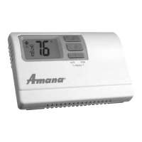
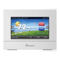
• 7-Day, 5-2-Day or 5-1-1-Day Programmable
• Congurable
• 2-Stage Heat/2-Stage Cool Systems
• 2-Stage Heat Pump Systems
• Large Display With Backlight
• Selectable Fahrenheit or Celsius
• Compatible with Gas, Oil, or Electric
• Relay Outputs
(minimum voltage drop in thermostat)
• Remote Sensor Compatible
• Ideally Suited for:
– Residential (New Construction/Replacement)
– Light Commercial
Installation, Operation &
Application Guide
www.amana-ptac.com
2246008
Programmable Electronic Thermostat
2 Heat/2 Cool, Auto Changeover, Hardwire
Press the CONFIG button for 2 seconds to exit conguration.