EasyManua.ls Logo

Amana DSA01NM - User Manual

Amana DSA01NM
4 pages
Print Icon
To Next Page IconTo Next Page
Loading...
PTAC
WIRELESS THERMOSTAT KIT (DSA01NM)
I
NSTALLATION INSTRUCTIONS
9/2015
IO-908A
Thermostat
Due to policy of continued product improvement, the right is reserved to change specifications and design without notice.
Heat in
g
& Air Co ndit ion in
g
®
A
5151 San Felipe, Suite 500 • Houston, TX 77056
www. ama na-p ta c. co m
© Copyright 2015 Go odman Co mpany, L. P.
is a registered trademark of Maytag Corporation or its related companies and is used
under license to Goodman Company, L.P., Houston, TX, USA. All rights reserved.
ATTENTION INSTALLING PERSONNEL
As a professional installer you have an obligation to know the
product better than the customer. This includes all safety
precautions and related items.
Prior to actual installation, thoroughly familiarize yourself
with this Instruction Manual. Pay special attention to all
safety warnings. Often during installation or repair it is
possible to place yourself in a position which is more
hazardous than when the unit is in operation.
Remember, it is your responsibility to install the product
safely and to know it well enough to be able to instruct a
customer in its safe use.
Safety is a matter of common sense...a matter of thinking
before acting. Most dealers have a list of specific good
safety practices...follow them.
The precautions listed in this Installation Manual are in-
tended as supplemental to existing practices. However, if
there is a direct conflict between existing practices and the
content of this manual, the precautions listed here take
precedence.
RECOGN I ZE THI S SYM BOL
AS A SAFETY PRECAUTI ON.
The following installation instructions are for a typical
installation.
Please contact your PTAC salesperson for additional assis-
tance and explanation prior to ordering materials or cutting
openings.
1. ANTENNA INSTALLATION FOR DSA01NM KIT
An antenna must be installed on the digital PTAC to allow
operation of the DSA01NM remote RF thermostat.
PREPARATION
1. Disconnect power to the unit by unplugging the power
cord at the wall outlet or subbase, or disconnect power
at the fuse box or circuit breaker.
2. If the cabinet front is screwed to the chassis, remove
the 1/4” screw (or screws). See following figure.
Radio - Non Mesh
Antenna
Question and Answer IconNeed help?

Do you have a question about the Amana DSA01NM and is the answer not in the manual?

Summary

Installation Safety and Preparation

Installer Responsibility and Safety

Emphasizes installer's obligation to know the product, safety precautions, and hazards.

Critical Safety Warning

Warns of high voltage and the need to disconnect all power before servicing.

Preparation Procedure

Details disconnecting power and accessing the unit's cabinet for installation.

Antenna Installation

Antenna Mounting and Connection

Steps for mounting the antenna housing and routing/connecting the cable to the control board.

Thermostat Installation and Setup

Thermostat Mounting Location

Guidance on selecting an optimal location for the thermostat, avoiding direct sunlight and heat sources.

Mounting Plate Installation

Instructions for attaching the thermostat mounting plate to the wall.

Thermostat Binding and Verification

Procedure to bind the wireless thermostat to the PTAC unit and verify operation.

General Functions and Configuration

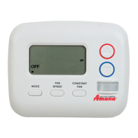
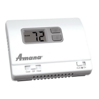
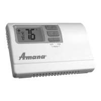
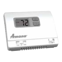
Explains the thermostat's mode button, backlight, and automatic self-configuration.

Compliance Information

FCC Compliance and RF Exposure

Details FCC authorization, rules, and required separation distance for RF exposure.

Overview

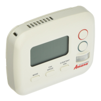
This document describes the installation and operation of the PTAC Wireless Thermostat Kit (DSA01NM), which includes a wireless thermostat and an antenna. The kit is designed to provide remote control of a PTAC (Packaged Terminal Air Conditioner) unit, enhancing user convenience and energy management capabilities.

Function Description

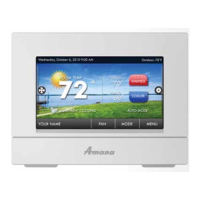
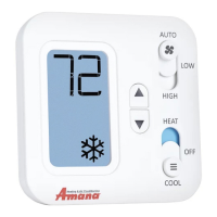
The DSA01NM kit enables wireless communication between a remote thermostat and a digital PTAC unit. The antenna, a crucial component, must be installed on the digital PTAC to facilitate this communication. Once installed and "bound" to the PTAC, the wireless thermostat allows users to remotely select operating modes (OFF, COOL, HEAT) and adjust settings without directly interacting with the PTAC unit's control panel. This is particularly useful in hotel rooms or other commercial settings where guests might prefer a wall-mounted thermostat for ease of access and operation. The system is designed to automatically self-configure once the thermostat is properly installed and bound, simplifying the setup process. The thermostat's backlight illuminates with the first button press, and subsequent presses of the MODE button cycle through the available operating modes. Any changes made on the wireless thermostat are automatically updated on the PTAC unit, ensuring synchronized control.

Usage Features

The wireless thermostat offers several user-friendly features:

  • Remote Control: The primary feature is the ability to control the PTAC unit from a wall-mounted thermostat, providing a more familiar and convenient interface than the unit's built-in controls.
  • Mode Selection: Users can easily switch between OFF, COOL, and HEAT modes using the MODE button on the thermostat.
  • Backlight: The thermostat features a backlight that activates with the first button press, improving visibility in low-light conditions.
  • Synchronized Control: Changes made on the wireless thermostat are automatically reflected on the PTAC unit, ensuring consistent operation.
  • Battery Powered: The thermostat is powered by four (4) AA batteries, making it independent of the PTAC unit's power supply and allowing for flexible placement.
  • Clear Display: Although not explicitly detailed, the presence of an LED display on the PTAC for binding confirmation suggests a clear interface for operational feedback.

For optimal performance, the thermostat should be mounted on an inside wall, about five feet above the floor, away from direct sunlight, radiant heat sources (lamps, fireplaces, other HVAC equipment), windows, or doors leading outside. It should also be placed in an area with good air circulation and out of the path of foot traffic to prevent accidental damage.

Maintenance Features

While the manual focuses primarily on installation and initial setup, some aspects touch upon maintenance:

  • Battery Replacement: The thermostat requires four (4) AA batteries, which will need periodic replacement. The manual provides instructions for installing these batteries, noting the importance of correct polarity.
  • Troubleshooting (Binding): The binding process includes steps for re-attempting the binding if the initial attempt is unsuccessful, indicating a built-in mechanism for resolving communication issues. The PTAC's LED display provides feedback during this process.
  • Diagnostic Review: After binding, the PTAC performs a diagnostic review, and the LED display returns to a blank screen, suggesting a self-check mechanism to ensure proper operation.
  • No User-Serviceable Parts: The manual explicitly states that the equipment contains no user-serviceable parts, and any modification or repair to internal components or the antenna configuration without express written consent could void the user's authority to operate the equipment. This emphasizes that maintenance beyond battery replacement should be handled by qualified personnel.
  • FCC Compliance: The device is designed to comply with FCC regulations, and the manual provides guidelines for maintaining this compliance, including a minimum separation distance of 20cm (8 inches) between the equipment and all persons. It also offers troubleshooting tips for interference, such as reorienting the receiving antenna or increasing separation from other devices.

The DSA01NM antenna is not designed to function with an occupancy sensor (DD01x) or in an RF mesh. If an energy management system or web-based monitoring is required, a DT01G RF wireless antenna (sold separately) must be installed. This distinction is important for understanding the scope of the kit's functionality and potential upgrade paths. The installation process involves careful handling of wires and connectors, with specific instructions to avoid bending or breaking them, which contributes to the longevity and reliability of the system.

Amana DSA01NM Specifications

General IconGeneral
TypeNon-Programmable
DisplayDigital
Temperature Range45°F to 90°F (7°C to 32°C)
BacklightNo
Hold FunctionYes
Power SourceBattery
CompatibilitySingle-stage heating and cooling systems

Related product manuals