Do you have a question about the Amana DT01 Series and is the answer not in the manual?
Essential safety precautions and responsibilities for installers of PTAC wireless kits.
Steps for mounting the DT01* antenna housing and connecting its wire harness to the PTAC unit.
Guidance on selecting an optimal location and mounting the DS01* thermostat.
Instructions for installing the DD01* motion sensor and its mounting plate.
Details on correctly positioning the door magnet holder relative to the DD01* sensor.
Step-by-step guide to pair wireless DS01* and DD01* devices with the PTAC unit.
How to access the PTAC control's configuration menu for setup.
Procedure for configuring the PTAC unit's room number identification.
Programming temperature and time setbacks for unoccupied room conditions using the DD01*.
Information on FCC regulations, interference, and RF exposure requirements for installation.
This document provides installation instructions for the Amana PTAC Wireless Kits (DT01*, DS01*, DD01*), which include an antenna, a remote RF thermostat, and a combination PIR motion sensor and door switch. These kits are designed to enhance the energy management and control capabilities of Amana Packaged Terminal Air Conditioner (PTAC) units.
The core function of these kits is to enable wireless communication and intelligent control over PTAC units, primarily for energy savings in commercial or hospitality settings. The DT01* antenna acts as the receiver for signals from the DS01* remote RF thermostat and the DD01* combination PIR motion sensor and door switch. The DS01* thermostat allows for remote temperature control, while the DD01* sensor detects room occupancy and door status, enabling automated setback temperatures to conserve energy when a room is unoccupied or a door is left open.
The installation process begins with the DT01* antenna, which must be physically installed into the PTAC unit. This involves disconnecting power, removing the cabinet front, drilling mounting holes, and securing the antenna housing. The antenna cable is then routed and plugged into the control board of the PTAC unit. Proper orientation of the LED on the antenna housing is crucial for correct operation.
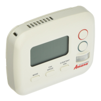
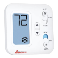
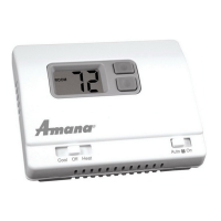
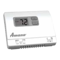
For the DS01* remote RF thermostat, careful consideration is given to its mounting location. It should be placed on an inside wall, approximately five feet above the floor, away from direct sunlight, heat sources, windows, and areas with poor air circulation. This ensures accurate temperature readings and prevents accidental damage. The installation involves mounting a back plate to the wall, and then installing two AAA batteries into the thermostat before snapping it onto the plate.
The DD01* combination PIR motion sensor and door switch requires a more intricate installation to ensure both motion detection and door status monitoring function correctly. The back plate of the sensor is mounted on the door trim directly above the door, as low as possible to be close to the moving part of the door without interfering with its operation. The magnet holder, which works in conjunction with the sensor, is mounted on the front of the door. The precise placement of the magnet holder and the magnet within its slots is critical to ensure the magnet is no more than 1/8" from the bottom center of the motion sensor when the door is closed. This precise alignment allows for proper detection of the door's open/close status. Similar to the thermostat, two AAA batteries are installed into the sensor.
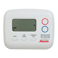
A crucial step after physical installation is the "binding" process, which establishes wireless communication between the DS01* thermostat, DD01* sensor, and the PTAC unit's DT01* control. This process must be performed with the PTAC unit in the OFF position. It involves pressing and holding the "OFF" button on the PTAC until a specific indicator appears, then immediately releasing the white tactile button on the back of the DS01* thermostat and/or the DD01* motion sensor. It's important to bind both devices (if present) simultaneously during the same "learn" operation. If a device is replaced or added, all previously bound devices must be re-bound to the unit. A significant caution is highlighted: "DO NOT ATTEMPT TO BIND MORE THAN ONE ROOM AT A TIME AT THE SAME PROPERTY!!!" as RF signals transmit through walls and can interfere with other units.
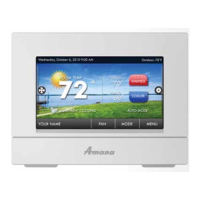
Once bound, the PTAC control automatically configures itself to work with the wireless devices. Further configuration allows for customization of energy management routines, including setback times and temperatures. To enter the configuration feature mode, a specific sequence of button presses on the PTAC touchpad is required. Within this mode, installers can navigate through various settings using the HEAT and COOL buttons and adjust values using the up and down arrows.
A key configuration option is setting the room number, particularly if using a DP01* Front Desk Platform. This involves selecting a 4-digit room number by adjusting the first two digits (floor) and then the last two digits using the HEAT button and arrow keys.
Setback Temperatures - DD01:*
The DD01* sensor enables the programming of up to three different times to activate temperature setbacks. These setbacks are designed to reduce energy consumption when a room is unoccupied. The manual details how to select the first, second, and third unoccupied setback temperatures and their corresponding setback times. The setback temperature is defined as the amount of degrees the control will operate from the guest's set point. For example, a 2° setback means the operational set point will be 2° higher than the guest's setting in cooling mode. The setback times are incremental, ranging from 6 minutes to 3 hours, determining how long after a room becomes unoccupied the setback temperature is activated. A critical warning is provided regarding the use of setback temperatures: "DO NOT USE MOTION SENSING SETBACK TEMPERATURES IN ROOMS WHERE INCAPACITATED PERSONS OR ANIMALS ARE UNABLE TO CHANGE THE CONTROL SETTING." This emphasizes the importance of safety and avoiding extreme temperature changes in rooms where occupants might be vulnerable.
The overall design of these wireless kits aims to provide a robust and flexible solution for managing PTAC units, focusing on user convenience and significant energy savings through intelligent, automated control.
| Type | Digital |
|---|---|
| Stages | 1 Heat/1 Cool |
| Voltage | 24V |
| Hold Feature | Yes |
| Filter Change Alert | Yes |
| Display | LCD |