EasyManua.ls Logo

Amana DS01E - User Manual

Amana DS01E
16 pages
Print Icon
To Next Page IconTo Next Page
Loading...
PTAC
WIRELESS KITS (DT01*, DS01E, DD01E, DD01F)
I
NSTALLATION INSTRUCTIONS
1/2013
IO-729C
The following installation instructions are for a typical installation.
Please contact your PTAC salesperson
for additional assistance and explanation prior to ordering materials or cutting openings.
DS01E
DD01E
DT01A
DT01G
ATTENTION INSTALLING PERSONNEL
As a professional installer you have an obligation to know the product better than the customer.
This includes all safety precautions and related items.
Prior to actual installation, thoroughly familiarize yourself with this Instruction Manual.
Pay special attention to all safety warnings. Often during installation or repair
it is possible to place yourself in a position which is more hazardous than when the unit is in operation.
Remember, it is your responsibility to install the product safely and to know it well enough
to be able to instruct a customer in its safe use.
Safety is a matter of common sense...a matter of thinking before acting.
Most dealers have a list of specific good safety practices...follow them.
The precautions listed in this Installation Manual are intended as supplemental to existing practices.
However, if there is a direct conflict between existing practices and the content of this manual,
the precautions listed here take precedence.
Heat in
g
& Air Conditionin
g
®
A
A
IR CONDITIONING SENSOR
DD01F
A
IR CONDITIONING SENSOR
PTAC Direct Sales, Inc.
185 S. Kimball Ave.
Suite 130
Southlake, TX 76092
877.454.7822 (T)
877.647.6408 (F)
Question and Answer IconNeed help?

Do you have a question about the Amana DS01E and is the answer not in the manual?

Summary

Attention Installing Personnel

Wireless Kit Installation

DT01* Antenna Installation

Guide for installing the DT01* antenna, essential for wireless communication with other devices.

DS01 E Thermostat Installation

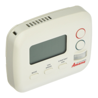
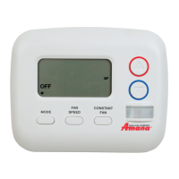
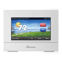
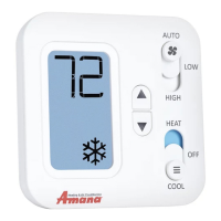
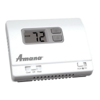
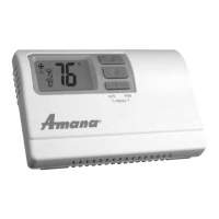
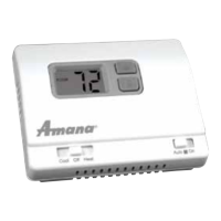
Steps for mounting and preparing the DS01E wireless thermostat for operation.

DS01 E Wired Power Option

Details on connecting wired power for the DS01E thermostat, including terminal connections and wire harness.

DD01 E;DD01 F Sensor and Door Magnet Installation

Instructions for mounting the DD01E/DD01F motion sensor and door magnet, including alignment.

DD01 E;DD01 F Wired Magnet and Powered Sensor Option

Instructions for wired magnet and powered door sensor options, including wiring and connection details.

System Configuration and Binding

DD01 E Door Sensor Operation Verification

Steps to verify proper installation and operation of the DD01E door sensor by checking its response to door open/close.

Standard and DS01 E Configuration

Guide to entering configuration mode and navigating settings for standard units and DS01E thermostat.

Entering Room Number for DP01*;DL01 E

Instructions for setting a 4-digit room number and suffix for DP01* or DL01E wireless platforms.

Binding of RF Devices

Procedure for binding wireless DS01E thermostat and DD01E motion sensor to the PTAC unit for communication.

Advanced Features and Location Guidance

DD01 E;DD01 F Setback Temperature Programming

Guide to programming three different times for temperature setbacks with DD01E/DD01F, detailing steps and examples.

Suggested Wireless Thermostat Locations

Recommendations for optimal thermostat mounting locations within typical room layouts, considering environmental factors.

Overview

This document describes the installation and configuration of the PTAC Wireless Kits, specifically models DT01*, DS01E, DD01E, and DD01F. These kits are designed to enhance the functionality of Packaged Terminal Air Conditioner (PTAC) units, primarily for energy management and remote control in hospitality or multi-room environments.

Function Description

The PTAC Wireless Kits integrate wireless communication and sensing capabilities with PTAC units.

  • DT01 Antenna:* This is a crucial component that enables wireless communication for other devices in the kit. It must be installed on the digital PTAC unit for the DS01* remote RF thermostat or the DD01* combination PIR motion sensor and door switch to operate.
  • DS01E Wireless Thermostat: This is a remote RF thermostat that allows users to control the PTAC unit wirelessly. It can be battery-powered or wired for continuous power. It also features a Passive Infrared (PIR) motion sensor, which can be used as a secondary motion sensor in conjunction with a DD01* device for enhanced occupancy detection.
  • DD01E/DD01F Combination PIR Motion Sensor and Door Switch: These devices combine a PIR motion sensor with a door switch. They are typically mounted on the door frame and detect room occupancy and door open/close status. This information is used by the PTAC unit to implement energy management routines, such as temperature setbacks when a room is unoccupied or a door is left open.

The system is designed to automatically self-configure for energy management routines when the DD01E or DD01F is installed and bound to the PTAC. This includes pre-configured setback times and temperatures, which can be adjusted. For properties using a DP01* or DL01E Front Desk Platform, the PTAC control needs to be configured with its room number placement for proper integration.

Important Technical Specifications

  • Wireless Platform: Utilizes DP01* or DL01E wireless platforms. Room numbers must be configured in the control board prior to binding wireless devices.
  • Power Supply (DS01E/DD01E/DD01F): Can be battery-powered (four AA batteries, included) or wired (20 gauge minimum field-supplied wires). For wired power, the PWHK01C wire harness kit is required to connect to the PTAC unit's C and R terminals.
  • Motion Sensor (PIR): Integrated into both the DS01E thermostat and the DD01E/DD01F door sensors. The DS01E's PIR can act as a second motion sensor.
  • Door Magnet: Used with DD01E/DD01F. The magnet holder has three slots (A, B, C) to achieve optimal alignment. The magnet must be positioned 15/16" from the back of the sensor mounting plate to its center. The space between the top of the magnet holder and the bottom of the DD01E/DD01F cannot exceed 1/8".
  • RF Transmission: Radio Frequency (RF) signals can transmit through walls up to 400 feet.
  • FCC Compliance: The equipment is authorized under United States Federal Communication Commission Rules and Regulations, Code of Federal Regulations Chapter 47 part 15. A minimum separation distance of 20cm (8 inches) is required between the equipment and all persons to comply with FCC RF exposure requirements.
  • Temperature Setback Defaults (v2.5 software):
    • 2° setback from set point in 30 minutes.
    • 3° setback from set point in 1 hour.
    • 6° setback from set point in 3 hours. These values can be changed through configuration settings.

Usage Features

  • Remote Control: The DS01E wireless thermostat allows users to adjust PTAC settings from a convenient location.
  • Energy Management: The DD01E/DD01F motion sensor and door switch enable automated temperature setbacks based on room occupancy and door status, reducing energy consumption.
  • Configuration Flexibility: Various settings can be configured, including:
    • Interface (C1): Chassis Membrane, Wireless Remote, Wired Thermostat.
    • Fan Operation (C2): Button present, 7-Button (reverts to Cyclic or Continuous), Always run fan.
    • Reverse Cycle Operation (C3): Cooler Only, Heat Pump, Service No Operation.
    • Room I.D. (C4, C5): 4-digit room number for integration with front desk platforms.
    • Wired or Wireless Occupancy (C6): Off, On, 18 Hour Automatic Entry.
    • Temperature Limiting (C8, C9): Cool (60°-72°), Heat (68°-90°, 80° default).
    • English / Metric Temp (Cd): Fahrenheit or Celsius Scale.
    • Unoccupied Setback (d6-dC): Configurable setback times (1st, 2nd, 3rd) and temperatures.
    • Room Prefix/Suffix (r4, r5): For multi-unit suites (e.g., master unit 01 suffix, slave units 02, 03).
  • Binding Process: A specific binding sequence is required to link wireless devices (DS01E, DD01E) to the PTAC unit. All devices for a single room must be bound at the same time.
  • Visual Indicators: The DS01E thermostat and DD01E/DD01F sensors have LEDs to indicate status (e.g., green light for closed door, off for open door).
  • Security Screws: Optional security screws are provided for the thermostat and motion sensor to prevent tampering.

Maintenance Features

  • Battery Replacement: The DS01E thermostat and DD01E/DD01F sensors use AA batteries, which will need periodic replacement if wired power is not used.
  • Rebinding Devices: If a wireless device is replaced or added, all devices (including previously bound ones) will need to be re-bound to the unit.
  • Software Version Check: The software version (e.g., v2.5) can be verified through a specific button sequence on the PTAC unit.
  • Troubleshooting: The manual provides guidance for verifying door sensor operation and general installation steps. For complex issues or additional configuration options, contacting the PTAC representative or manufacturer is recommended.
  • Safety Warnings: Emphasizes disconnecting power before servicing, avoiding motion sensing setbacks in rooms with incapacitated persons or animals, and adhering to FCC guidelines.

Amana DS01E Specifications

General IconGeneral
BrandAmana
ModelDS01E
CategoryThermostat
LanguageEnglish

Related product manuals