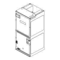
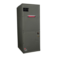
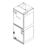
AMVE
AIR HANDLERS
INSTALLATION & OPERATING INSTRUCTIONS
1 Important Safety Instructions ..............................................................2
2 Shipping Inspection .............................................................................3
2.1 Parts .....................................................................................................3
2.2 Handling ...............................................................................................3
3 Codes & Regulations ...........................................................................3
4 Replacement Parts ...............................................................................3
5 Pre-Installation Considerations ..........................................................3
5.1 Preparation ...........................................................................................3
5.2 System Matches ...................................................................................3
5.3 Interconnecting Tubing .........................................................................3
5.4 Clearances ...........................................................................................3
5.5 Horizontal Applications .........................................................................4
6 Installation Location .............................................................................4
6.1 Upow Installation ................................................................................4
6.2 Horizontal Left Installation ....................................................................4
6.3 Downow/Horizontal Right Installation .................................................4
7 Refrigerant Lines ..................................................................................7
7.1 Tubing Size ........................................................................................... 7
7.2 Tubing Preparation ...............................................................................7
7.3 Tubing Connections .............................................................................. 7
8 Condensate Drain Lines ......................................................................8
9 Ductwork ...............................................................................................9
9.1 Return Ductwork ................................................................................... 9
10 Return Air Filters ................................................................................9
11 Electric Heat ........................................................................................9
12 Electrical and Control Wiring .......................................................... 11
12.1 Building Electrical Service Inspection ............................................... 11
12.2 Wire Sizing ....................................................................................... 11
12.3 Maximum Overcurrent Protection (MOP) ......................................... 11
12.4 Electrical Connections – Supply Voltage ......................................... 12
12.4.1 Air Handler Only (Non-Heat Kit Models) ........................................12
12.4.2 Air Handler - Non-Circuit Breaker Heat Kits ..................................12
12.4.3 Air Handler With Circuit Breaker Heat Kit ...................................... 12
12.5 Low Voltage Connections ................................................................. 12
13 Achieving 1.4% & 2% Low Leakage Rate ....................................... 12
14 Miscellaneous Start-Up Checklist ................................................... 12
14.1 Circulator Blower ..............................................................................14
14.2 AMVE Motor Orientation ...................................................................14
15 Troubleshooting ...............................................................................15
15.1 Electrostatic Discharge (ESD) Precautions .................................... 15
16 CoolCloud HVAC Phone Application ..............................................15
17 Quick Start Guide for Communicating
Outdoor Units ...................................................................................15
17.1 Charging ...........................................................................................16
18 Electric Heater Kit Testing ............................................................... 16
19 Dehumidication ..............................................................................16
20 Auxiliary Alarm Switch ..................................................................... 16
21 Push Buttons ....................................................................................16
22 Accessory Control (Humidiers, Dehumidiers,
Ventilators) ........................................................................................17
23 Ramping Proles ..............................................................................17
24 Electric Air Cleaning ........................................................................18
25 Air Handler Troubleshooting Matrix ...............................................19
25 Air Handler Troubleshooting Matrix (Continued) ..........................20
26 Air Handler Display ..........................................................................21
26 Air Handler Display (Continued) .....................................................22
26 Air Handler Display (Continued) .....................................................23
27 Wiring Diagram .................................................................................24
28 Dehumidication Control Options ...................................................25
29 Start-Up Checklist .............................................................................27
ONLY PERSONNEL THAT HAVE BEEN TRAINED TO INSTALL,
ADJUST, SERVICE OR REPAIR(HEREINAFTER, “SERVICE”)
THE EQUIPMENT SPECIFIED IN THIS MANUAL SHOULD
SERVICE THE EQUIPMENT. THE MANUFACTURER WILL
NOT BE RESPONSIBLE FOR ANY INJURY OR PROPERTY
DAMAGE ARISING FROM IMPROPER SERVICE OR SERVICE
PROCEDURES. IF YOU SERVICE THIS UNIT, YOU ASSUME
RESPONSIBILITY FOR ANY INJURY OR PROPERTY
DAMAGE WHICH MAY RESULT. IN ADDITION, IN
JURISDICTIONS THAT REQUIRE ONE OR MORE LICENSES
TO SERVICE THE EQUIPMENT SPECIFIED IN THIS
MANUAL, ONLY LICENSED PERSONNEL SHOULD SERVICE
THE EQUIPMENT.
IMPROPER INSTALLATION, ADJUSTMENT, SERVICING OR
REPAIR OF THE EQUIPMENT SPECIFIED IN THIS MANUAL,
OR ATTEMPTING TO INSTALL, ADJUST, SERVICE OR REPAIR
THE EQUIPMENT SPECIFIED IN THIS MANUAL WITHOUT
PROPER TRAINING MAY RESULT IN PRODUCT DAMAGE,
PROPERTY DAMAGE, PERSONAL INJURY OR DEATH.
WARNING
This device, which was assembled by Daikin Comfort Technologies
L.P., contains a component that is classied as an intentional radiator.
This intentional radiator has been certied by the FCC: FCC ID
QOQBGM111. And this international radiator has an Industry Canada ID:
IC 5123A-BGM111.
This device complies with Part 15 of the FCC’s Rules. Operation of this
device is subject to two conditions:
(1) This device may not cause harmful interference; and
(2) This device must accept any interference received, including
interference that may cause undesirable operation.
And this device meets the applicable Industry Canada technical
specications.
The manufacturer of the intentional radiator (model no. BGM111) is
Silicon Laboratories Finland Oy, which can be contacted by calling 617-
951-0200. (www.silabs.com)
Daikin Comfort Technologies, L.P. may be contacted by calling 713-861-
2500, or at 19001 Kermier Rd., Waller TX 77484.
(www.DaikinComfort.com)
WARNING
DO NOT BYPASS SAFETY DEVICES
© 2022 Daikin Comfort Technologies Manufacturing, L.P.
19001 Kermier Rd., Waller, TX 77484
www.goodmanmfg.com - or - www.amana-hac.com
P/N: IOA-4040 Date: December 2022
is a registered trademark of Maytag Corporation or its related companies and is used under license. All rights reserved.