EasyManua.ls Logo

Amana AHVE Series - User Manual

Amana AHVE Series
28 pages
Print Icon
To Next Page IconTo Next Page
Loading...
IOA-4039A
12/2022
1 Important Safety Instructions ............................................................... 2
2 Shipping Inspection ...............................................................................3
2.1 Parts ........................................................................................................3
2.2 Handling ..................................................................................................3
3 Codes & Regulations ............................................................................. 3
4 Replacement Parts.................................................................................3
5 Pre-Installation Considerations ........................................................... 3
5.1 Preparation .............................................................................................. 3
5.2 System Matches ...................................................................................... 3
5.3 Interconnecting Tubing ............................................................................4
5.4 Clearances ..............................................................................................4
5.5 Horizontal Applications ............................................................................ 4
6 Installation Location ............................................................................. 4
6.1 Upow Installation ................................................................................... 4
6.2 Horizontal Left Installation ....................................................................... 4
6.3 Downow/Horizontal Right Installation .................................................... 8
7 Refrigerant Lines ................................................................................... 8
7.1 Tubing Size .............................................................................................. 8
7.2 Tubing Preparation ..................................................................................8
7.3 Tubing Connections ................................................................................. 9
8 Condensate Drain Lines ........................................................................ 9
9 Ductwork...............................................................................................10
9.1 Return Ductwork .................................................................................... 10
10 Return Air Filters ................................................................................ 10
11 Electric Heat .......................................................................................10
12 Electrical and Control Wiring ............................................................12
12.1 Building Electrical Service Inspection .................................................. 12
12.2 Wire Sizing ..........................................................................................12
12.3 Maximum Overcurrent Protection (MOP) ............................................ 12
12.4 Electrical Connections – Supply Voltage ............................................. 12
12.4.1 Air Handler Only (Non-Heat Kit Models) ........................................... 12
12.4.2 Air Handler - Non-Circuit Breaker Heat Kits ..................................... 12
12.4.3 Air Handler With Circuit Breaker Heat Kit ......................................... 13
12.5 Low Voltage Connections .................................................................... 13
13 Achieving 1.4% & 2% Low Leakage Rate ........................................ 13
  ........................................................................................13
15 Miscellaneous Start-Up Checklist .................................................... 14
15.1 Auxiliary Alarm Switch .........................................................................15
15.2 Circulator Blower ................................................................................. 15
15.3 Motor Orientation ................................................................................. 15
15.4 Accessory Contacts ............................................................................. 16
 ..................................................................................16
16.1 Electrostatic Discharge (ESD) Precautions ....................................... 16
16.2 Diagnostic Chart ................................................................................. 16
16.3 Fault Recall.........................................................................................16
17 Fully Communicating Amana System ............................................... 17
17.1 Overview..............................................................................................17
17.2 Airow Consideration ........................................................................... 17
17.3 Thermostat Wiring ...............................................................................17
17.3.1 Two-Wire Outdoor and Four-Wire Indoor Wiring .........................18
17.4 Network Troubleshooting ..................................................................... 18
17.5 System Troubleshooting ...................................................................... 18
 ........................................................................................20
Diagnostic Codes ......................................................................................22
 ......................................................................... 23
Wiring Diagram .......................................................................................... 25
Routine Maintenance ................................................................................ 26
Start-Up Checklist ..................................................................................... 27

If an “Ed” error is encountered
on startup, verify that the
electric heater DIP switches



and DIP switch settings.
 

© 2022 Daikin Comfort Technologies Manufacturing, L.P.
19001 Kermier Rd., Waller, TX 77484
www.goodmanmfg.com - or - www.amana-hac.com
P/N: IOA-4039A Date: December 2022
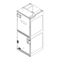
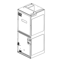
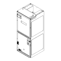
AHVE
AIR HANDLERS
INSTALLATION & OPERATING INSTRUCTIONS





DAMAGE ARISING FROM IMPROPER SERVICE OR SERVICE













WARNING
is a registered trademark of Maytag Corporation or its related companies and is used under license.
All rights reserved.
WARNING


Other manuals for Amana AHVE Series

Question and Answer IconNeed help?

Do you have a question about the Amana AHVE Series and is the answer not in the manual?

Summary

AHVE Air Handler Installation and Operating Instructions

Important Safety Instructions

Provides critical safety warnings and precautions for handling and installing the air handler.

Shipping Inspection and Handling

Procedures for inspecting the unit upon receipt and guidelines for safe handling during transport.

Codes and Regulations Compliance

Details on adhering to national, local, and state codes for proper installation.

Replacement Parts Information

Guidance on identifying and ordering necessary replacement parts for the unit.

Pre-Installation Considerations

Essential checks and preparations before starting the installation process.

Installation Location Guidelines

Recommendations and requirements for selecting an appropriate installation site for the air handler.

Refrigerant Line Installation

Instructions for the proper installation and connection of refrigerant lines.

Condensate Drain Line Setup

Proper methods for installing and routing condensate drain lines to ensure effective drainage.

Ductwork Installation Requirements

Guidelines for sizing, sealing, and installing supply and return ductwork.

Return Air Filter Installation

Information on the necessity and method of installing return air filters.

Electric Heat Kit Installation

Procedures and compatibility information for installing optional electric heat kits.

Electrical and Control Wiring

Comprehensive guide for all electrical connections, wiring, and supply voltage requirements.

Achieving Low Airflow Leakage Rates

Steps to ensure the unit meets specified low airflow leakage rates for optimal efficiency.

Airflow Trim Adjustment

Guidance on adjusting indoor airflow settings for performance optimization.

Start-Up Checklist and Procedures

A detailed checklist of final checks and procedures before operating the unit.

Troubleshooting Common Issues

Guidance for diagnosing and resolving operational problems, error codes, and alerts.

Fully Communicating Amana System Operation

Overview of features and operation for systems using communicating thermostats.

Overview

This document provides comprehensive installation and operating instructions for AHVE Air Handlers, manufactured by Daikin Comfort Technologies Manufacturing, L.P. The manual emphasizes safety, proper installation procedures, and maintenance for optimal performance and longevity of the unit.

Function Description:

The AHVE Air Handler is designed for indoor installation and serves as a crucial component of a complete heating, ventilation, and air conditioning (HVAC) system. It is responsible for circulating conditioned air throughout a building, working in conjunction with an outdoor air conditioner or heat pump. The unit supports various configurations, including upflow, downflow, horizontal left, and horizontal right orientations, offering flexibility for different installation requirements. It is equipped with an electronic expansion valve (EEV) for precise refrigerant control and a variable-speed circulator blower for efficient airflow management. The system is designed to be part of a fully communicating Amana system, allowing for two-way digital communication between the indoor unit, outdoor unit, and thermostat for enhanced control and diagnostics.

Important Technical Specifications:

  • Installation Altitude: Designed for indoor installation only, at a maximum altitude of 10,500 feet above sea level or a minimum altitude of -184 feet below sea level.
  • Operating Conditions:
    • Cooling Mode: 150°F max and 40°F min ambient surrounding cabinet.
    • Heating Mode: 90°F max and 0°F min ambient surrounding cabinet.
  • Refrigerant: Factory-shipped with R410A and dry nitrogen mixture gas under pressure.
  • Drain Pan Connections: Primary and secondary drains with 3/4" NPT female connections.
  • Ductwork: Designed for a complete supply and return ductwork system, sized to accommodate 350-450 CFM per ton of cooling with static pressure not exceeding 0.5” in w.c. Flame retardant ductwork is required.
  • Electrical Supply: Single-phase electrical supply only (208/240V). Not designed for three-phase power.
    • Nominal Input Voltage: 208-240V
    • Minimum Voltage: 197V
    • Maximum Voltage: 253V
  • Low Voltage Wiring: N.E.C Class 2 Wire, typical 18 AWG thermostat wire. Maximum 250 feet between indoor and outdoor unit, and 125 feet between indoor unit and thermostat.
  • Airflow Leakage Rate: Achieves less than 1.4% airflow leakage @ 0.5 inch wc static pressure and less than 2% airflow leakage @ 1 inch wc static pressure when tested in accordance with ASHRAE Standard 193.
  • Heater Kit Options: Compatible with HKS series heat kits. Specific kW ratings and corresponding CFM values are provided in tables for 208V, 240V, and 230V supply voltages.
  • Accessory Relay: Equipped with a 1½ inch accessory relay with normally open terminals (ACC-IN and ACC-OUT) for peripheral devices like humidifiers. Max ratings: 10A 250VAC, 5A 30VDC.
  • Diagnostic Display: 2-digit 7-segment LED display on the Printed Circuit Board (PCB) for error codes and system status.

Usage Features:

  • Flexible Installation: Supports upflow, downflow, horizontal left, and horizontal right configurations. Field modifications are required for downflow and horizontal right installations, including coil assembly reorientation and specific drain pan adjustments.
  • Condensate Management: Features primary and secondary drain ports. A secondary drain pan is required for installations above finished living spaces. A condensate trap with a positive liquid seal is mandatory to prevent air draw-through and ensure proper drainage.
  • Return Air Filters: Each installation requires a return air filter. The unit supports nominal 16x20x1", 20x20x1", or 24x20x1" filters on factory filter rails, or external filter grilles.
  • Electric Heat Integration: Designed to integrate with optional HKS series electric heat kits. Heater kit capacity can be set via the communicating thermostat user menu or DIP switches on the control board.
  • Communicating System: When part of a fully communicating Amana system, the indoor unit, outdoor unit, and thermostat interact digitally for two-way communication, enabling advanced control and diagnostics. Airflow demands are managed by the system operating mode, with the thermostat, heat pump, or air handler determining the demand.
  • Airflow Trim: Indoor airflow can be trimmed up/down through the outdoor unit user menu, with positive side trim settings allowed within specified maximum CFM values to prevent condensation blow-off.
  • Auxiliary Alarm Switch: Equipped with terminals (TB4 and TB5) for connection to normally closed auxiliary alarm devices like condensate switches, CO2 sensors, or fire alarms. The system responds to an open switch by turning off the blower and outdoor unit and displaying fault codes.
  • Motor Orientation: For downflow installations, the motor must be rotated to ensure female connections face downwards, preventing water collection and premature failure.
  • Diagnostic Tools: The integrated control module features a 7-segment LED display for active fault codes and a "Fault Recall" button to display the last six faults. A "Learn" button is available to reset the network.
  • Humidifier Relay: The accessory relay can be configured for humidification functionality, either active only during a heat call, always off, or cycling with any active call for humidification (independent of a heat call), with selectable fan speeds.

Maintenance Features:

  • Filter Replacement/Cleaning: Regular inspection (at least monthly) and replacement or cleaning of return air filters are crucial for maintaining efficiency and preventing equipment damage.
  • Coil Cleaning: The aluminum tube evaporator coil should be flushed with water for cleaning. The use of corrosive chemicals (e.g., chlorine, hydroxides) is strictly prohibited as they can cause premature coil failure. Approved cleaners listed in TP-109 can be used.
  • Motor Lubrication: Indoor and outdoor fan motors are permanently lubricated and do not require additional oiling.
  • Electrical Safety: Emphasizes disconnecting all power before servicing and using appropriate service tools. Proper grounding and wire sizing are critical.
  • Troubleshooting: A detailed troubleshooting chart is provided, correlating PCB LED display codes with possible causes and corrective actions for various operational problems.
  • Fault History: The "Fault Recall" button allows users to view the last six system faults and clear the error code history.
  • Routine Maintenance Recommendations: Strongly recommends bi-annual maintenance checkups by a qualified servicer before heating and cooling seasons.
  • ESD Precautions: Instructions are provided to discharge static electricity before touching electrical components to prevent damage.

Amana AHVE Series Specifications

General IconGeneral
BrandAmana
ModelAHVE Series
CategoryAir Handlers
LanguageEnglish

Related product manuals