10
Water coming from secondary line means the coil
primary drain is plugged and needs immediate attention.
Insulate drain lines located inside the building or above a n-
ished living space to prevent sweating. Install a condensate
trap to ensure proper drainage.
When units are installed above ceilings, or in other
locations where damage from condensate overow may occur,
it is to install a eld fabricated auxiliary drain
pan under the coil cabinet enclosure.
The installation must include a “P” style trap that is located
as close as is practical to the indoor unit coil. See Figure 12
for details of a typical condensate line “P” trap.
Units operating in high static pressure applications may
require a deeper eld constructed “P” style trap than is shown
in Figure 12 to allow proper drainage and prevent condensate
overow.
Trapped lines are required by many local codes. In
the absence of any prevailing local codes, please refer to the
requirements listed in the Uniform Mechanical Building Code.
A drain trap in a draw-through application prevents air from
being drawn back through the drain line during fan operation
thus preventing condensate from draining, and if connected
to a sewer line to prevent sewer gases from being drawn into
the airstream during blower operation.
Use of a condensate removal pump is permitted when nec-
essary. This condensate pump should have provisions for
shutting o the control voltage should a blocked drain occur.
See Auxiliary Alarm Switch section for more details. A trap
must be installed between the unit and the condensate pump.
The evaporator coil is fabricated with
oils that may dissolve styrofoam and certain types of plastics.
Therefore, a removal pump or oat switch must not contain
any of these materials.
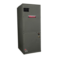
This air handler is designed for a complete supply and return
ductwork system.
To ensure correct system performance, the ductwork is to be
sized to accommodate 350-450 CFM per ton of cooling with
the static pressure not to exceed 0.5” in w.c. Refer to ACCA
Manual D, Manual S and Manual RS for information on duct
sizing and application. Flame retardant ductwork is to be used
and sealed to the unit in a manner that will prevent leakage.
A downow application with electric heat must have
an L-shaped sheet metal supply duct without any outlets or
registers located directly below the heater.
9.1 Return Ductwork
DO NOT LOCATE THE RETURN DUCTWORK IN AN
AREA THAT CAN INTRODUCE TOXIC, OR OBJEC-
TIONABLE FUMES/ODORS INTO THE DUCTWORK.
The return ductwork is to be connected to the air handler
bottom (upow conguration).
Each installation must include a return air lter. This ltering
may be performed at the air handler using the factory lter rails
or externally such as a return air lter grille. When using the
factory lter rails, a nominal 16x20x1”, 20x20x1” or 24x20x1”
(actual dimension must be less than 23-½”x20”) lter can be
installed on a B, C and D cabinet respectively (the cabinet
size is the seventh letter of the model number). Washable
versions are available through your local distributor.
Refer to the installation manual provided with the electric
heat kit for the correct installation procedure. All electric heat
must be eld installed. If installing this option, the ONLY heat
kits that are permitted to be used are the HKS series. Refer
to the air handler unit’s Serial and Rating plate or the HKS
specication sheets to determine the heat kits compatible with
a given air handler. No other accessory heat kit besides the
HKS series may be installed in these air handlers.
TRANSFORMER SUB-ASSEMBLY
Before installing the Heat Kit, uninstall the transformer sub-as-
sembly (Figure 13). Make sure to unplug 12-Pin connector
before uninstalling the uninstalling the transformer sub-as-
sembly. Follow the Heat Kit Installation Manual to install the
Heat Kit. Install transformer sub-assembly back to the unit
(Figure 13). Plug in 12-Pin connectors and secure screws
while installing transformer sub-assembly back to the unit
after heater kit installation.
The heating mode temperature rise is dependent upon the
system airow, the supply voltage, and the heat kit size (kW)
selected. Use data provided in Tables 4, 5 and 6 to determine
the temperature rise (°F).
For emergency heat, set the dipswitch on PCB. For
heating mode, use the thermostast user menu.
For installations not indicated above the following formula is
to be used:
TR = (kW x 3412) x (Voltage Correction) / (1.08 x CFM)
Where: TR = Temperature Rise
kW = Heater Kit Actual kW
3412 = Btu per kW
VC* = 1.0 (240 Supply Volts)
= .92 (230 Supply Volts)
= .84 (220 Supply Volts)
= .77 (210 Supply Volts)
= .75 (208 Supply Volts)
1.08 = Constant
CFM = Measured Airow
*VC (Voltage Correction)
 Loading...