18
Please read carefully before installing this unit.
• Power line terminal #C from Indoor unit must connect
to terminal #C on thermostat and power line terminal
#R from indoor unit must connect to terminal #R on
thermostat. Verify wires are not reversed.
• Do not attach any wires to the R & C Terminals on
the AC/HP, as they are not needed for inverter unit.
The order of the terminals of the indoor unit
and the Amana Smart Thermostat thermostat may
be dierent.)
• Data line terminal #1 from AC/HP must connect to
terminal #1 on indoor unit and thermostat and data
line terminal #2 from AC/HP must connect to terminal
#2 on indoor unit and thermostat. Verify wires are not
reversed.
17.3.1 Two-Wire Outdoor and Four-Wire Indoor
Wiring
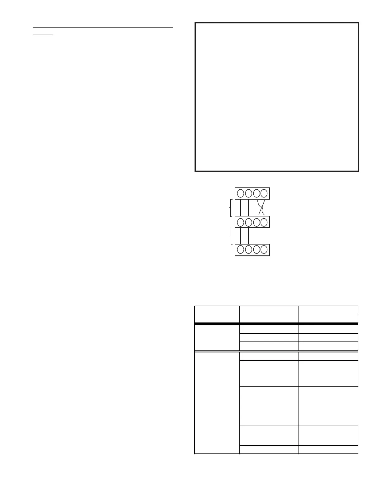
Typical wiring will consist of two wires between the
indoor unit and outdoor unit and four wires between
the indoor unit and thermostat. Figure 20 shows the
required wires are: data lines, 1 and 2; “R” (24 VAC
hot) and “C” (24 VAC common).
17.4 Network Troubleshooting
Occasionally the need to troubleshoot the network may
arise. The integrated air handler control has some on-
board tools that can be used to troubleshoot the network.
These tools are: red communications LED, green receive
(Rx) LED, and the learn button. Refer to the Communi-
cations Troubleshooting Chart at the end of this manual
for error codes, possible causes and corrective actions
• Red communications LED – Indicates the status of
the network. The Communications Troubleshooting
Chart on the following page indicates the LED status
and the corresponding potential problem.
• Green receive LED – Indicates network trac. The
following table indicates the LED status and the corre-
sponding potential problem.
• Learn button – Used to reset the network. Depress
the button for approximately 2 seconds to reset the
network.
17.5 System Troubleshooting
Refer to the instructions accompanying the
Communicating compatible outdoor AC/HP unit for
unit specic troubleshooting information. Refer to the
Troubleshooting Chart at the end of this manual for
a listing of possible air handler error codes, possible
causes and corrective actions.
SYSTEM WIRING
Figure 20
1 2 C R
1 2 R C
1 2 R C
Communicang Thermostat
125 .(*)
Air Handler Blower Integrated
Control Module
250 .(*)
Heat Pump Integrated
Control Module
(*) Allowable Maximum Length
1 2 C R
1 2 R C
1 2 R C
Communicang Thermostat
125 .(*)
Air Handler Blower Integrated
Control Module
250 .(*)
Heat Pump Integrated
Control Module
(*) Allowable Maximum Length
Cooling Air Conditioner
Heating Air Handler
Continuous Fan Thermostat
Cooling Heat Pump
Greater than of Heat
Pump of Air Handler
Demand
Electric Heat Strips
Only
Air Conditioner +
Air Handler
Table 11
 Loading...