13
A terminal block is provided with the HKS kit to attach
the power supply and air handler connections. Follow
the HKS Installation Manual and wiring diagram for
complete wiring details.
12.4.3 Air Handler With Circuit Breaker Heat Kit
The air handler has a soft plastic cover on the upper
access panel and can be removed to allow the heater
kit circuit breaker to be installed. The circuit breakers
have lugs for power supply connection. See the HKS
Installation Instructions for further details.
12.5 Low Voltage Connections
Use N.E.C Class 2 Wire. The 24V-control voltage con-
nects the air handler to the room thermostat and outdoor
unit. Typical 18 AWG thermostat wire may be used to
wire the system components. Two hundred fty (250)
feet is the maximum of wire between indoor unit and
outdoor unit, and one hundred twenty ve (125) feet
between indoor unit and thermostat. Low voltage wiring
must be copper conductors. Low voltage wiring must be
connected through the top of the cabinet or either side.
See the “Thermostat Wiring” section of this manual for
typical low voltage wiring connections.
13 ACHIEVING 1.4% AND 2.0% AIRFLOW LOW
Ensure all the gaskets remain intact on all surfaces as shipped
with the unit. These surfaces are areas between the upper tie
plate and coil access panel, blower access and coil access
panels, and between the coil access and lter access pan-
els. Ensure upon installation, that the plastic breaker cover
is sitting ush on the blower access panel and all access
panels are ush with each other and the cabinet. With these
requirements satised, the unit achieves less than 1.4%
airow leakage @ 0.5 inch wc static pressure and less than
2% airow leakage @1inch wc static pressure when tested
in accordance with ASHRAE Standard 193.
: After installing the heater kits, it is very import-
ant to seal the gap between the circuit breaker and the cover.
Putty paste or gasket can be used to seal the gap so that air
leakage can be minimized.
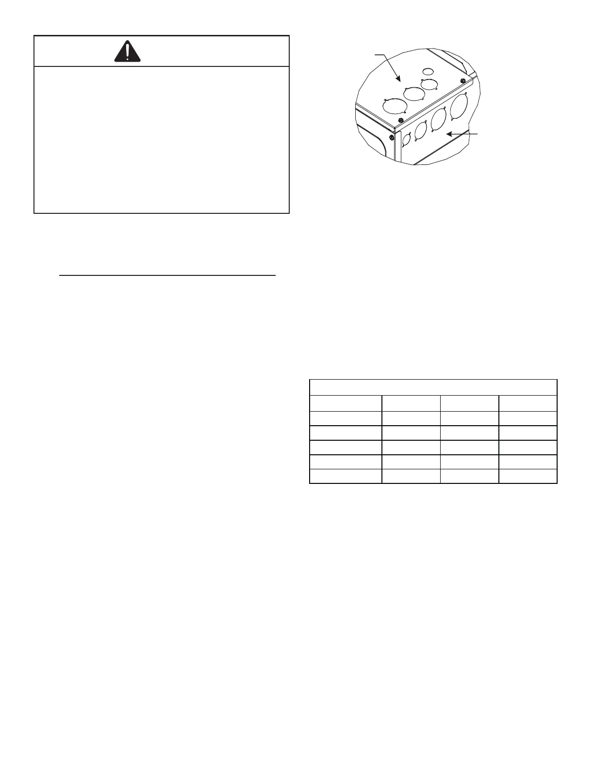
Side of
Cabinet
Top of
Cabinet
KNOCK-OUT FOR ELECTRICAL
CONNECTIONS
Figure 14
Indoor airow can be trimmed up/down through the outdoor
unit user menu. For more detailed information, please refer
to the outdoor unit installation manual.
• To prevent condensation blow o, positive side trim
settings are allowed within the Maximum CFM listed
below. The CFM in this table intends actual measured
value at installation site. Do not refer to the CFM value
in the outdoor spec sheet, displayed in status menu
of communication thermostat, or the displayed LEDs
on the PCB, as there may be a tolerance dierence
between displayed and actual measured.
Up-Flow Down-Flow HZ-Flow
AHVE24BP1400 910 870 870
AHVE36CP1400 1450 1390 1390
AHVE42CP1400 1520 1450 1450
AHVE48DP1400 1590 1520 1520
AHVE60DP1400 1890 1800 1800
Maximum Measured CFM Allowed
WARNING
 Loading...