8
6.3 Downow/Horizontal Right Installation
In the downow application, to
prevent coil pan “sweating”, the mandatory downow
kit (DFK) is available through your local distributor. The
DFK is not supplied with the air handler and is required
to minimize pan sweating on all downow installations.
See Table 3 for the correct DFK and follow the instructions
provided for installation.
used when installing the unit in Horizontal Right
Refer to Figure 7 and 8 for the location of the components
referenced in the following steps.
1. Before ipping the air handler, remove blower access
panel and coil access panel. The coil access panel and
tubing panel may remain screwed together during this
procedure. Remove and retain the seven (7) screws
securing the coil access panel to the cabinet and the
six (6) screws securing the blower access panel to the
cabinet.
2. Before removing the coil remove the wire ties holding the
sensor wire harness to the center support. Remove the
insulation covering the wire connectors and disconnect
the wires. Do not cut or damage the insulation covering
the junction connectors since it will be required to secure
the wires once the change is complete. See Figures 2-1
and 2-2 for wire tie location.
3. Slide the coil assembly out using the bottom drain pan
to pull the assembly from the cabinet.
4. For ipping the coil, drain pan extension must be re-
moved for all models. Center support should not be
removed while removing the drain pan extension. Side
drain pan and horizontal drip shield can be removed for
downow application. The side drain pan and horizontal
drip shield cannot be removed for horizontal right.
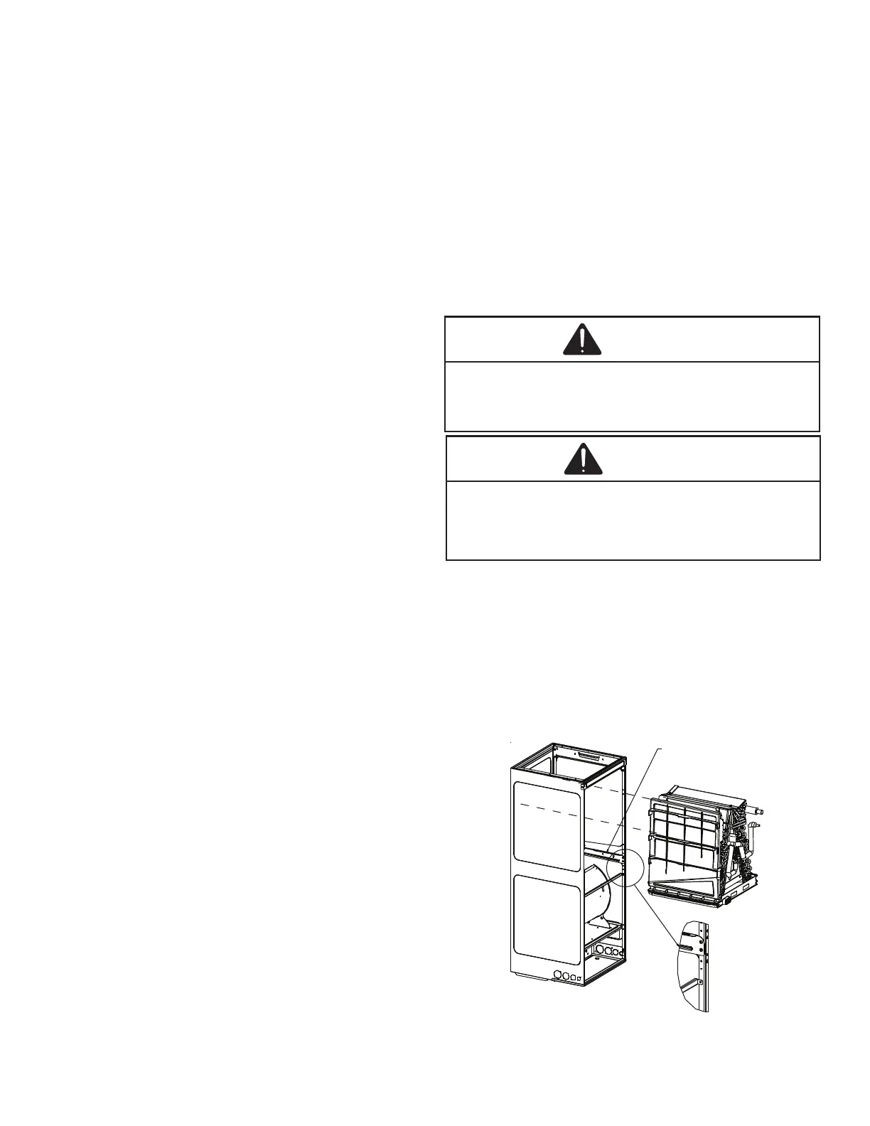
5. Using the bottom drain pan to hold the coil assembly,
slide the coil assembly back into the cabinet on the
downow brackets as shown in Figure 9.
6. Reconnect the sensor wires and replace the insulation
securing it with wire ties on both sides as shown in Figure
2-2. Then, secure the wire harness to the corner post
using the screw mount wire ties provided.
7. Re-install the access panels removed in Step 1 as shown
in Figure 10.
Figure 9
8. Two drain ports located at the bottom drain pan (horizon-
tally oriented) are to be used for upow and downow
applications and the two on the side drain pan (vertically
oriented) are to be used when the unit is in horizontal
right or left conguration. When the unit is in upow or
downow conguration, the drain ports located on bot-
tom drain pan must be plugged and vice versa. Drain
ports located at lower elevation (closer to the ground)
in either conguration must be connected to the main
drain line and the higher is for the secondary drain line.
Care should be taken to route refrigerant tubing in a
way which allows adequate access for servicing and main-
tenance of the air handling unit.
WARNING
WARNING
7.1 Tubing Size
For the correct tubing size, refer to the outdoor AIR
CONDITIONING OR HEAT PUMP INSTALLATION &
SERVICE REFERENCE.
7.2 Tubing Preparation
All cut ends are to be round, burr free, and clean. Failure
to follow this practice increases the chances for refriger-
ant leaks. The suction line is spun closed and requires
tubing cutters to remove the closed end.
COIL INSTALLATION FOR DOWNFLOW
IMPORTANT NOTE:
Ensure coil slides on the rails along the groove provided
on the drain pan sid e walls. Failu re to do so will result in
improper condensate drainage.
Coil slides on
the downow bracket
 Loading...