9
To prevent possible damage to the tubing joints,
do not handle coil assembly with manifold or owrator
tubes. Always use clean gloves when handling coil
assemblies.
The use of a heat shield is strongly recommend-
ed when brazing to avoid burning the serial plate or the
nish of the unit. Heat trap or wet rags must be used
to protect heat sensitive components such as service
valves, electronic expansion valve (EEV), thermistors
and pressure sensors.
7.3 Tubing Connections
EEV Series Air Handler models come with factory installed
electronic expansion valve (EEV) pre-installed on the
liquid tube.
1 Remove refrigerant tubing panel or coil (lower) ac-
cess panel.
2. Remove access valve tting cap and depress the
valve stem in access tting to release pressure. No
pressure indicates possible leak.
3. Replace the refrigerant tubing panel.
4. Remove the spin closure on both the liquid and
suction tubes using a tubing cutter.
5. Insert liquid line set into liquid tube expansion and
slide grommet about 18” away from braze joint.
6. Insert suction line set into suction tube expansion
and slide insulation and grommet about 18” away
from braze joint.
7. Braze joints. Quench all brazed joints with water or
a wet rag upon completion of brazing.
8. Replace access panels, suction line grommet, insu-
lation and all screws.
The use of a heat shield is strongly recommended
when brazing to avoid burning the serial plate or the nish
of the unit. Heat trap or wet rags must be used to protect
heat sensitive components such as service valves, electronic
expansion valve (EEV), thermistors and pressure sensors.
The coil drain pan has a primary and a secondary drain with
3/4” NPT female connections. The connectors required are
3/4” NPT male, either PVC or metal pipe, and should be hand
tightened to a torque of no more than 37 in-lbs. to prevent
damage to the drain pan connection. An insertion depth of
approximately 3/8” to 1/2” (3-5 turns) should be expected at
this torque.
1. Ensure drain pan hole is not obstructed.
2. To prevent potential sweating and dripping on to nished
space, it may be necessary to insulate the condensate
drain line located inside the building. Use Armaex
®
or
similar material.
A secondary condensate drain connection has been provided
for areas where the building codes require it. Pitch all drain
lines a minimum of 1/4” per foot to provide free drainage.
Provide required support to the drain line to prevent bowing.
If the secondary drain line is required, run the line separately
from the primary drain and end it where condensate discharge
can be easily seen.
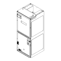
ACCESS PANEL CONFIGURATION FOR DOWNFLOW
OR HORIZONTAL RIGHT
Figure 10
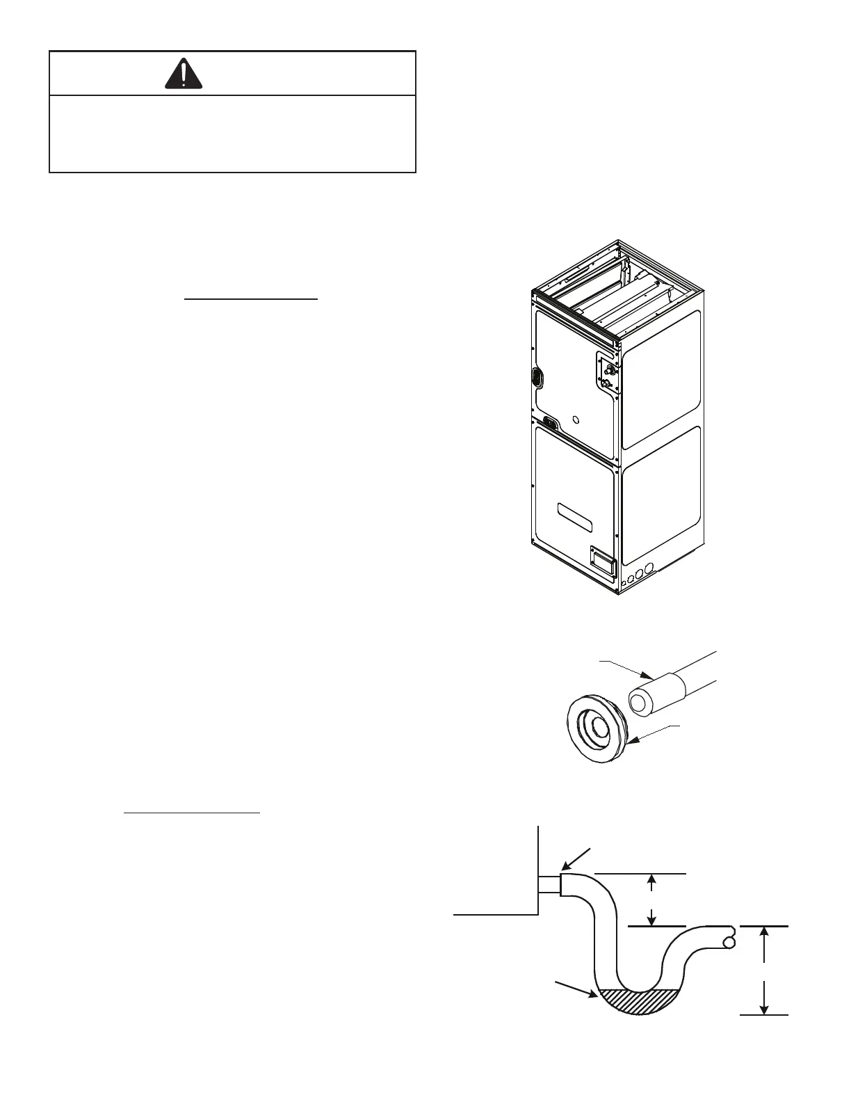
RUBBER
GROMMET
SUCTION LINE
WITH SPIN CLOSURE
SUCTION LINE GROMMET
Figure 11
Figure 12
POSITIVE LIQUID
SEAL REQUIRED
AT TRAP
 Loading...