Installation Instructions
9 RA233001 Rev. 3
C22.1, Canadian Electric Code, Part 1. In Canada, the
installation must conform with CSA standards Z240.6.1
electrical requirements for mobile homes.
The wiring diagram is located behind the control panel
taped to the side of the oven near the gas pressure regu-
lator.
The receptacle should be checked by an authorized
electrician to make sure it is properly grounded. This
should be a 120 volt, 60hz, properly grounded, three-
prong receptacle protected by a 15-amp circuit breaker
or time delay fuse.
The power supply cord on double gas wall ovens is
equipped with a three-prong (grounding) plug for protec-
tion against shock hazard. It should be plugged into a
properly grounded receptacle.
If there is any doubt as to whether the wall receptacle is
properly grounded, the customer should have it checked
by an authorized service electrician. Where a standard
two-prong wall receptacle is encountered, it is the per-
sonal responsibility and obligation of the customer to
have it replaced with a properly grounded three-prong
wall receptacle.
Before the final gas connection is made and the oven is
position, the electrical supply cord should be plugged
into the receptacle. Do not turn the power on at the main
circuit breaker until the final gas connection is made. In
the event of a power failure, the oven cannot be oper-
ated.
DANGER
!
To avoid the risk of electrical shock or fire, a three-
wire grounded conductor system must be used.
Relying upon the gas line for ground may result in
fire or expose persons to the risk of electric shock as
well as erratic control operation.
Place Oven in Opening
Slide the oven on its cardboard shipping base to the
cabinet opening.
1. One person should lean the oven to the side.
2. A second person must remove the four screws from
the shipping base. Discard the screws and the ship-
ping base.
3. Remove the oven doors by pulling them up and off
the oven.
4. One person should be positioned on each side of
the unit. Grasping the unit inside the lower oven and
on the bottom, lift it into the cabinet opening.
5. Plug in the power cord and push the oven back into
the cabinet. Do not pinch the power cord.
6. Locate the holes in the oven frame. Drill 1/8-inch
pilot into the cabinet front and secure the oven using
the four screws provided.
Oven Screw Locations
Screw Location
Final Gas Connection
The electrical supply should be turned off at the main
circuit breaker before attempting to make the final gas
connection.
The gas supply line assembled earlier must be con-
nected to the pressure regulator on the oven. To gain
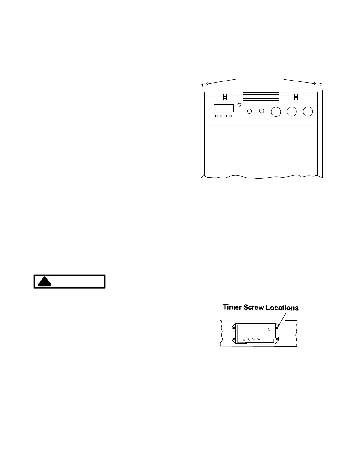
access to the pressure regulator, the control panel and
timer must be removed.
1. Remove knobs from the timer and control panel by
pulling them straight out.
2. Remove two screws securing control panel in place
as indicated in the illustration below.
3. Remove four screws holding the timer in place.
4. Pull the timer forward and place it on the top oven
rack. There should not be any stress placed on the
harness connections.
5. Connect the supply line to the regulator using a
1/2-inch nipple, union and elbow. The supply line
should be accessed by reaching through the open-
ing in the control panel area and through the upper
cabinet doors or removable panel. Use two
 Loading...