8
The rating plate is stamped with the model number, type of
gas and gas input rating. Make sure the unit is equipped to
operate on the type of gas available. Conversion to LP gas
is permitted with the use of the factory authorized conver-
sion kit LPM-07, for use with single stage models, or LPM-
08, for use with two-stage models. See table below.
LP Conversion Kit Model
LPM-07 Single Stage Heating Models
LPM-08 Two-Stage Heating Models
Inlet Gas Pressure
Natural Min. 5.0" W.C., Max. 10.0" W.C.
Propane
Min. 11.0" W.C., Max. 13.0" W.C.
Inlet Gas Pressure must be within the minimum and maxi-
mum value shown in table above.
The minimum supply pressure should not vary from that
shown in the table above because this could prevent the
unit from having dependable ignition. In addition, gas input
to the burners must not exceed the rated input shown on
WKHUDWLQJSODWH2YHU¿ULQJRIWKHXQLWFRXOGUHVXOWLQSUHPD-
ture heat exchanger failure.
+එඏඐ$ඔගඑගඝඌඍ'ඍකඉගඍ86,ඖඛගඉඔඔඉගඑඖඛ2ඖඔඡ
,03257$17127(7ඐඍඏඉඛඍඔඍඋගකඑඋඝඖඑගඛඖඉගඝ-
කඉඔඔඡඌඍකඉගඍඟඑගඐඉඔගඑගඝඌඍ'ඖගඉගගඍඕගග
එඖඋකඍඉඛඍගඐඍඎඑකඑඖඏකඉගඍඊඡඋඐඉඖඏඑඖඏකඑඎඑඋඍඛක
එඖඋකඍඉඛඑඖඏගඐඍඕඉඖඑඎඔඌකඍඛඛඝකඍ7ඐඑඛඋඉඖඋඉඝඛඍ
කඋඕඊඝඛගඑඖඉඖඌඍඝඑඕඍඖගඎඉඑඔඝකඍ$ගඉඔඔ
ඉඔගඑගඝඌඍඛගඐඍඕඉඖඑඎඔඌකඍඛඛඝකඍඕඝඛගඊඍඟඑගඐඑඖ
එඖඋඐඍඛ:&ඎගඐඉගඔඑඛගඍඌඖගඐඍඖඉඕඍඔඉගඍ
ඎකගඐඍඎඝඍඔඝඛඍඌ$ගඉඔඔඉඔගඑගඝඌඍඛඉඖඌඟඑගඐඍඑගඐඍක
ඎඝඍඔගඐඍඉඑකගඍඕඍකඉගඝකඍකඑඛඍඕඝඛගඊඍඟඑගඐඑඖගඐඍ
කඉඖඏඍඔඑඛගඍඌඖගඐඍඝඖඑගඖඉඕඍඔඉගඍ
Refer to the Installation Manual provided with the LP kit for
conversion from natural gas to propane gas and for altitude
adjustments. NOTE: Up to 2,000 feet, no changes are
required; above 2,000 feet, please refer to the gas/electric
SDFNDJHXQLWVSHFL¿FDWLRQVKHHWVIRUUHTXLUHGNLWV8VH
HA03 for installations above 2000’.
Installation of the gas/electric unit at altitudes above 2000
IWPVKDOOEHPDGHLQDFFRUGDQFHZLWKWKHOLVWHG+LJK
Altitude Conversion Kit available for this gas/electric unit.
3එඑඖඏ
,03257$17127(7ඉඞඑඌඛඛඑඊඔඍඝඖඛඉගඑඛඎඉඋගකඡ
ඍකඉගඑඖකඍඝඑඕඍඖගඌඉඕඉඏඍඌඝඍගඝඖඌඍකඎඑකඑඖඏ
ඎඍඝඑඕඍඖගඌඖගඝඖඌඍකඛඑජඍගඐඍඖඉගඝකඉඔකඉඖඍ
ඏඉඛඑඑඖඏඎකඕගඐඍඕඍගඍකගඉඖඓගගඐඍඝඖඑග:ඐඍඖ
ඛඑජඑඖඏඉගකඝඖඓඔඑඖඍඑඖඋඔඝඌඍඉඔඔඉඔඑඉඖඋඍඛඖගඐඉග
ඔඑඖඍගඐඉගඋඝඔඌඊඍඍකඉගඍඌඛඑඕඝඔගඉඖඍඝඛඔඡ
The rating plate is stamped with the model number, type of
gas and gas input rating. Make sure the unit is equipped to
operate on the type of gas available. The gas line instal-
lation must comply with local codes, or in the absence of
local codes, with the latest edition of the National Fuel Gas
Code NFPA 54/ANSI Z223.1.
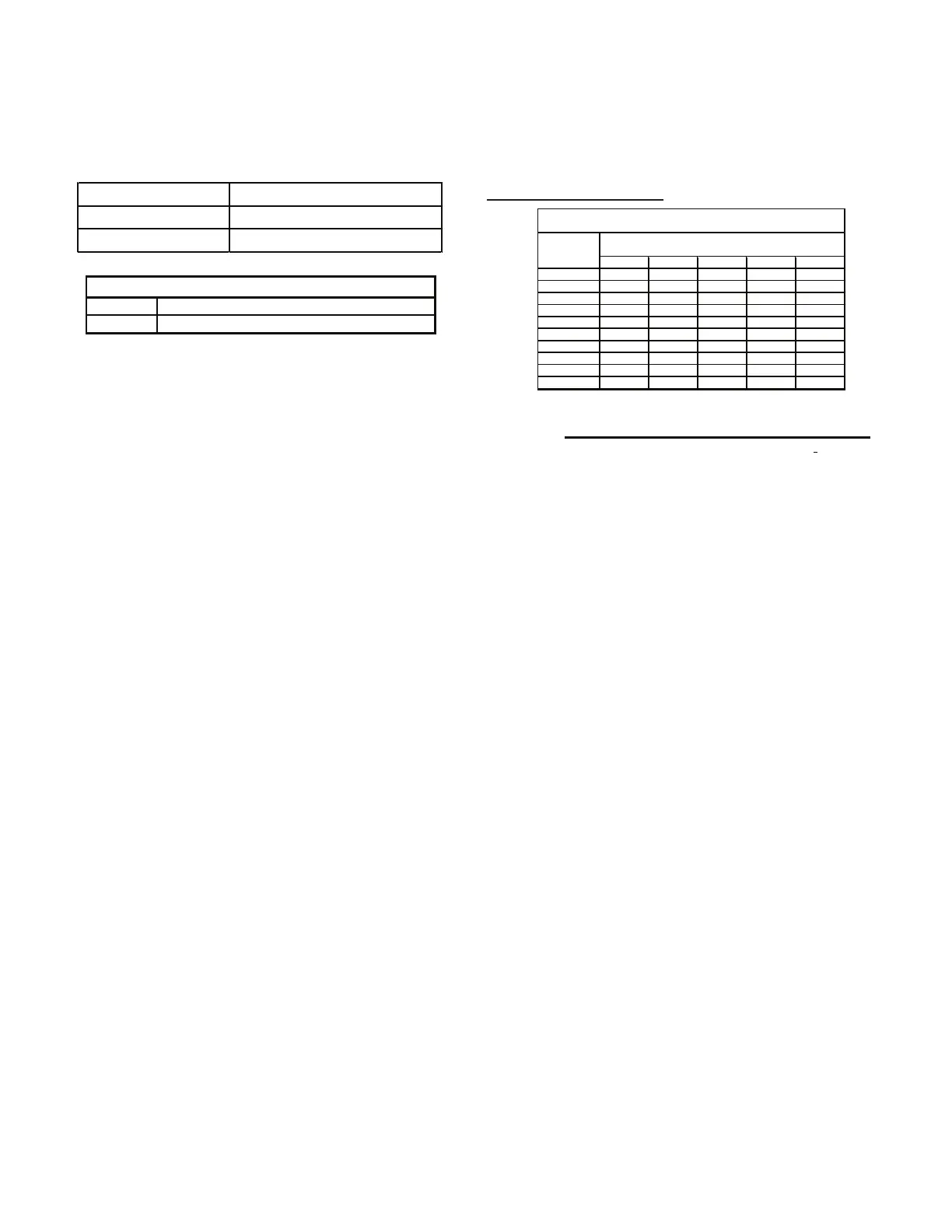
Natural Gas Connection
Pipe in Feet
1/2 3/4
1
1 1/4 1 1/2
10 132 278 520 1050 1600
20 92 190 350 730 1100
30 73 152 285 590 980
40 63 130 245 500 760
50 56 115 215 440 670
60 50 105 195 400 610
70 46 96 180 370 560
80 43 90 170 350 530
90 40 84 160 320 490
3UHVVXUH 36,*RUOHVVDQG3UHVVXUH'URSRI:&%DVHG
RQ6SHFLILF*UDYLW\*DV
Natural Gas Capacity of Pipe
LQ&XELF)HHWRI*DV3HU+RXU&)+
1RPLQDO%ODFN3LSH6L]HLQFKHV
&DORULILF9DOXHRI*DV
+HDWLQJ9DOXHRI*DV%78&XELF )RRW
Refer to the Proper Piping Practice drawing for the general
OD\RXWDWWKHXQLW7KHIROORZLQJUXOHVDSSO\
1. 8VHEODFNLURQSLSHDQG¿WWLQJVIRUWKHVXSSO\SLSLQJ
7KHXVHRIDÀH[FRQQHFWRUDQGRUFRSSHUSLSLQJ
is permitted as long as it is in agreement with local
codes.
2. Use pipe joint compound on male threads only. Pipe
joint compound must be resistant to the action of the
fuel used.
3. Use ground joint unions.
4. Install a drip leg to trap dirt and moisture before it can
enter the gas valve. The drip leg must be a minimum
of three inches long.
5. Use two pipe wrenches when making connection to
the gas valve to keep it from turning.
6. ,QVWDOODPDQXDOVKXWRႇYDOYHLQDFRQYHQLHQWORFDWLRQ
ZLWKLQVL[IHHWRIXQLWEHWZHHQWKHPHWHUDQGWKHXQLW
7. Tighten all joints securely.
8. The unit must be connected to the building piping by
RQHRIWKHIROORZLQJPHWKRGV
• 5LJLGPHWDOOLFSLSHDQG¿WWLQJV
• 6HPLULJLGPHWDOOLFWXELQJDQGPHWDOOLF¿WWLQJV
$OXPLQXPDOOR\WXELQJPXVWQRWEHXVHGLQH[WHULRU
ORFDWLRQV
• Listed gas appliance connectors used in accordance
with the terms of their listing that are completely in the
same room as the equipment
• In the prior two methods above the connector or
tubing must be protected from physical and thermal
damage. Aluminum alloy tubing and connectors must
be coated to protect against external corrosion when
in contact with masonry, plaster or insulation or are
VXEMHFWWRUHSHDWHGZHWWLQJVE\OLTXLGVZDWHUQRW
UDLQZDWHUGHWHUJHQWVRUVHZDJH
 Loading...