10
See below for typical propane gas piping.
200 PSIG
Maximum
WR36,*
36,*0D[
Continuous
11" W.C.
Second Stage
Regulator
First Stage
Regulator
7ඡඑඋඉඔ3කඉඖඍ*ඉඛ3එඑඖඏ
Sizing Between First and Second Stage Regulator
Maximum Propane Capacities listed are based on 1 PSIG Pressure Drop at 10
PSIG Setting. Capacities in 1,000 BTU/HR
3/8" 1/2" 3/4" 7/8" 1/2" 3/4"
30 309 700 1,303 2,205 3,394 1,843 3,854
40 265 599 1,115 1,887 2,904 1,577 3,298
50 235 531 988 1,672 2,574 1,398 2,923
60 213 481 896 1,515 2,332 1,267 2,649
70 196 446 824 1,394 2,146 1,165 2,437
80 182 412 767 1,297 1,996 1,084 2,267
90 171 386 719 1,217 1,873 1,017 2,127
100 161 365 679 1,149 1,769 961 2,009
150 130 293 546 923 1,421 772 1,613
200 111 251 467 790 1,216 660 1,381
250 90 222 414 700 1,078 585 1,224
300 89 201 378 634 976 530 1,109
350 82 185 345 584 898 488 1,020
400 76 172 321 543 836 454 949
To convert to Capacities at 15 PSIG Settings -- Multiply by 1.130
To convert to Capacities at 5 PSIG Settings -- Multiply by 0.879
120,1$/3,3(6,=(
SCHEDULE 40
78%,1*6,=(2'7<3(/
6L]LQJ%HWZHHQ6LQJOHRU6HFRQG6WDJH5HJXODWRUDQG$SSOLDQFH
Maximum Propane Capacities Listed are Based on 1/2" W.C. Pressure Drop at
11" W.C. Setting. Capacities in 1,000 BTU/HR
3/8" 1/2" 3/4" 7/8" 1/2"
10 49 110 206 348 539 291 608 1,146 2,353 3,525
20 34 76 141 239 368 200 418 788 1,617 2,423
30 27 61 114 192 296 161
336 632 1,299 1,946
40 23 52 97 164 253 137 284 541 1,111 1,665
50 20 46 86 146 224 122 255 480 985 1,476
60 19 42 78 132 203 110 231 436 892 1,337
80 16 36 67 113 174 94 198 372 764 1,144
100 14 32 59 100 154 84 175 330 677 1,014
125 12 28 52 89 137 74 155 292 600 899
150 11 26 48 80 124 67 141 265 544 815
200 10 22 41 69 106 58 120 227 465 697
250 9 19
36 61 94 51 107 201 412 618
300 8 18 33 55 85 46 97 182 374 560
350 7 16 30 51 78 43 89 167 344 515
400 7 15 28 47 73 40 83 156 320 479
'$7$,1$&&25'$1&(:,7+1)3$3$03+/(712
120,1$/3,3(6,=(
SCHEDULE 40
78%,1*6,=(2'7<3(/
7ඉඊඔඍ3කඉඖඍ*ඉඛ3එඍ6එජඑඖඏ
WARNING
7කඍඞඍඖගකඍකගඡඌඉඕඉඏඍකඛඍකඑඝඛඍකඛඖඉඔඑඖඒඝකඡඌඝඍ
ගඎඑකඍකඍචඔඛඑඖඋඉඝඛඍඌඊඡකඉඖඍඏඉඛඔඍඉඓඑඖඛගඉඔඔඉඏඉඛ
ඌඍගඍඋගඑඖඏඟඉකඖඑඖඏඌඍඞඑඋඍ,ඎගඐඍකඉඖඍඏඉඛඝඖඑගඑඛඑඖඛගඉඔඔඍඌ
එඖඉඖඍචඋඉඞඉගඍඌඉකඍඉකඉඋඖඎඑඖඍඌඛඉඋඍඉඟඉකඖඑඖඏඌඍඞඑඋඍඑඛ
කඍඝඑකඍඌඌඝඍග
• 3කඉඖඍඏඉඛඑඛඐඍඉඞඑඍකගඐඉඖඉඑකඉඖඌඉඖඡඔඍඉඓඑඖඏඏඉඛඋඉඖ
ඛඍගගඔඍඑඖඉඖඡඔඟඉකඍඉඛකඋඖඎඑඖඍඌඛඉඋඍඛ
• 3කඉඖඍඏඉඛඌකඉඖගඕඉඡඎඉඌඍඕඉඓඑඖඏගඐඍඏඉඛ
ඝඖඌඍගඍඋගඉඊඔඍඍචඋඍගඟඑගඐඉඟඉකඖඑඖඏඌඍඞඑඋඍ
ELECTRICAL WIRING
7ඐඍකඕඛගඉග/උඉගඑඖ
0RXQWWKHWKHUPRVWDWDSSUR[LPDWHO\¿YHIHHWDERYHWKH
ÀRRULQDQDUHDWKDWKDVDQLQVLGHYLEUDWLRQIUHHZDOODQG
has good air circulation.
Movement of air must not be obstructed by furniture, door,
draperies, etc. The thermostat must not be mounted where
LWZLOOEHDႇHFWHGE\GUDIWVKRWRUFROGZDWHUSLSHVRUDLU
GXFWVLQZDOOVUDGLDQWKHDWIURP¿UHSODFHODPSVWKHVXQ
television, etc. Consult the Instruction Sheet packaged with
thermostat for mounting instructions.
WARNING
HIGH VOLTAGE
'එඛඋඖඖඍඋගඉඔඔඟඍකඊඍඎකඍඛඍකඞඑඋඑඖඏක
එඖඛගඉඔඔඑඖඏගඐඑඛඝඖඑග0ඝඔගඑඔඍඟඍකඛඝකඋඍඛ
ඕඉඡඊඍකඍඛඍඖග)ඉඑඔඝකඍගඌඛඕඉඡඋඉඝඛඍ
කඍකගඡඌඉඕඉඏඍඍකඛඖඉඔඑඖඒඝකඡකඌඍඉගඐ
Five ton models have two stages of heating and two stages
of mechanical cooling. Units which have economizers may
use thermostats with two or three stages of cooling.
All other units have one stage of heating and one stage of
mechanical cooling. Units which have economizers may
use thermostats with one or two stages of cooling.
The units are designed for operation on 60 hertz current
and at voltages as shown on the rating plate. All internal
wiring in the unit is complete. It is necessary to bring in the
power supply to the contactor as shown on the unit wiring
diagram which is supplied with each unit. 24 volt wiring
must be connected between the unit control panel and the
room thermostat.
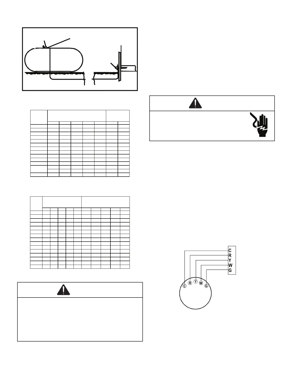
7ඐඍකඕඛගඉග:එකඑඖඏ6එඖඏඔඍ6ගඉඏඍ0ඌඍඔඛ
From
Unit
6එඖඏඔඍ6ගඉඏඍ+ඍඉගඑඖඏ຺&ඔඑඖඏ7ඐඍකඕඛගඉග'එඉඏකඉඕ
7ඐඍකඕඛගඉග:එකඑඖඏ7ඟ6ගඉඏඍ0ඌඍඔඛ
 Loading...