8
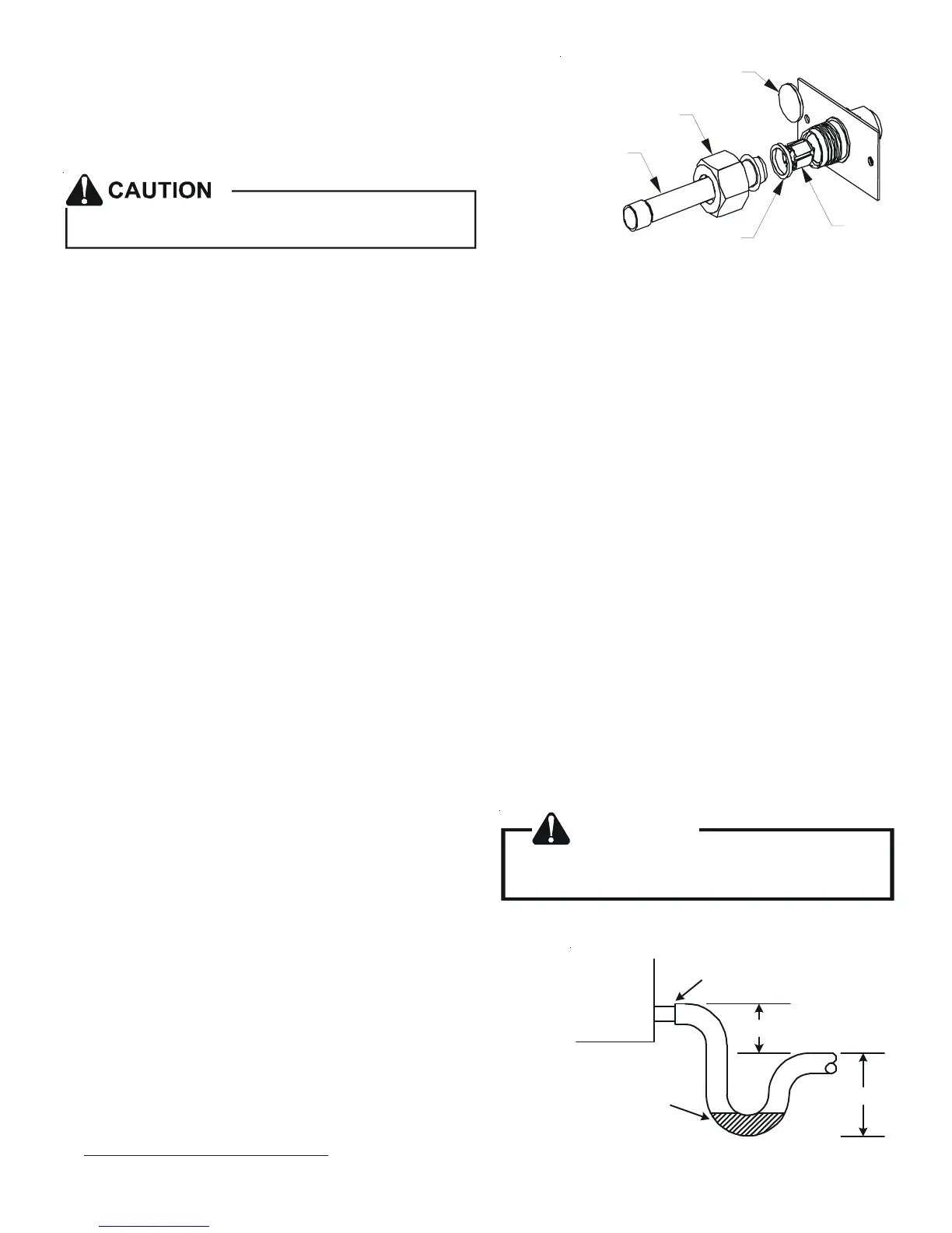
Excessive torque can cause orifices to stick. Use the
proper torque settings when tightening orifices.
WHITE
TEFLON SEAL
PISTON
TAILPIECE
13/16” NUT
PLASTIC or BRASS CAP
TAILPIECE JOINT
Figure 11
8. AFTER THE TAILPIECE HAS COOLED, confirm position of the white
Teflon
®
seal and hand tighten the 13/16 nut.
9. Torque the 13/16 nut to 7-25 ft-lbs. or tighten 1/6 turn.
7.5 Tubing Connections for TXV Models
TXV models come with factory installed TXV with the bulb pre-
installed on the vapor tube.
1. Remove refrigerant tubing panel or coil (lower) access panel.
2. Remove access valve fitting cap and depress the valve stem in access fitting to release pressure. No pressure indi-
cates possible leak.
3. Replace the refrigerant tubing panel.
4. Remove the spin closure on both the liquid and suction tubes using a tubing cutter.
5. Insert liquid line set into liquid tube expansion and slide grommet about 18" away from braze joint.
6. Insert suction line set into suction tube expansion and slide insulation and grommet about 18" away from braze joint.
7. Braze joints. Quench all brazed joints with water or a wet rag upon completion of brazing.
8 Condensate Drain Lines
The coil drain pan has a primary and a secondary drain with 3/4" NPT female connections. The connectors required are 3/
4" NPT male, either PVC or metal pipe, and should be hand tightened to a torque of no more than 37 in-lbs. to prevent
damage to the drain pan connection. An insertion depth of approximately 3/8” to 1/2” (3-5 turns) should be expected at
this torque.
1. Ensure drain pan hole is not obstructed.
2. To prevent potential sweating and dripping on to finished space, it may be necessary to insulate the condensate drain
line located inside the building. Use Armaflex
®
or similar material.
A secondary condensate drain connection has been provided for areas where the building codes require it. Pitch all drain
lines a minimum of 1/4" per foot to provide free drainage. Provide required support to the drain line to prevent bowing.
If the secondary drain line is required, run the line separately
from the primary drain and end it where condensate discharge
can be easily seen.
NOTE: Water coming from secondary line means the coil pri-
mary drain is plugged and needs immediate attention.
Insulate drain lines located inside the building or above a fin-
ished living space to prevent sweating. Install a condensate
trap to ensure proper drainage.
NOTE: When units are installed above ceilings, or in other locations
where damage from condensate overflow may occur, it is MANDATORY
to install a field fabricated auxiliary drain pan under the coil cabinet
enclosure.
The installation must include a “P” style trap that is located as close as
is practical to the evaporator coil. See Figure 12 for details of a typical
condensate line “P” trap.
NOTE: Trapped lines are required by many local codes. In the absence
of any prevailing local codes, please refer to the requirements listed in
the Uniform Mechanical Building Code.
CAUTION
If secondary drain is not installed, the secondary
access must be plugged.
Air Handler
3" MIN.
POSITIVE LIQUID
SEAL REQUIRED
AT TRAP
Drain
Connection
2" MIN.
Figure 12
 Loading...