SERVICING
44
5. With the system still running, remove hose and reinstall both
valve caps.
6. Check system for leaks.
NOTE: Subcooling information is valid only while the unit is operat-
ing at 100% capacity or 100% of compressor speed in CHARGE MODE.
Compressor speed is displayed under STATUS menu in the thermo-
stat.
S-104 CHECKING COMPRESSOR EFFICIENCY
The reason for compressor inefficiency is that the compressor is
broken or damaged, reducing the ability of the compressor to
pump refrigerant vapor.
The condition of the compressor is checked in the following man-
ner.
1. Attach gauges to the high and low side of the system.
2. Start the system and run CHARGE MODE.
If the test shows:
a.
Below normal high side pressure.
b. Above normal low side pressure.
c. Low temperature difference across coil.
d. Low amp draw at compressor.
And the charge is correct. The compressor is faulty - replace the
compressor.
S-109 CHECKING SUBCOOLING
Refrigerant liquid is considered subcooled when its temperature
is lower than the saturation temperature corresponding to its
pressure. The degree of subcooling equals the degrees of tem-
perature decrease below the saturation temperature at the exist-
ing pressure.
1. Attach an accurate thermometer or preferably a thermocouple
type temperature tester to the liquid service valve as it leaves
the condensing unit.
2. Install a high side pressure gauge on the high side (liquid)
service valve at the front of the unit.
3. Record the gauge pressure and the temperature of the line.
4. Review the technical information manual or specification
sheet for the model being serviced to obtain the design
subcooling.
5. Compare the hi-pressure reading to the "Required Liquid Line
Temperature" chart. Find the hi-pressure value on the left col-
umn. Follow that line right to the column under the design
subcooling value. Where the two intersect is the required liq-
uid line temperature.
Alternately you can convert the liquid line pressure gauge
reading to temperature by finding the gauge reading in R-410A
Pressure vs. Temperature Chart, find the temperature in the °F.
Column.
6. The difference between the thermometer reading and pressure
to temperature conversion is the amount of subcooling.
ADD CHARGE TO RAISE SUBCOOLING. RECOVER CHARGE
TO LOWER SUBCOOLING.
Subcooling Formula = Sat. Liquid Temp. - Liquid Line Temp.
EXAMPLE:
a. Liquid Line Pressure = 417 PSIG
b. Corresponding Temp. = 120°F.
c. Thermometer on Liquid line = 109°F.
To obtain the amount of subcooling subtract 109°F from 120°F.
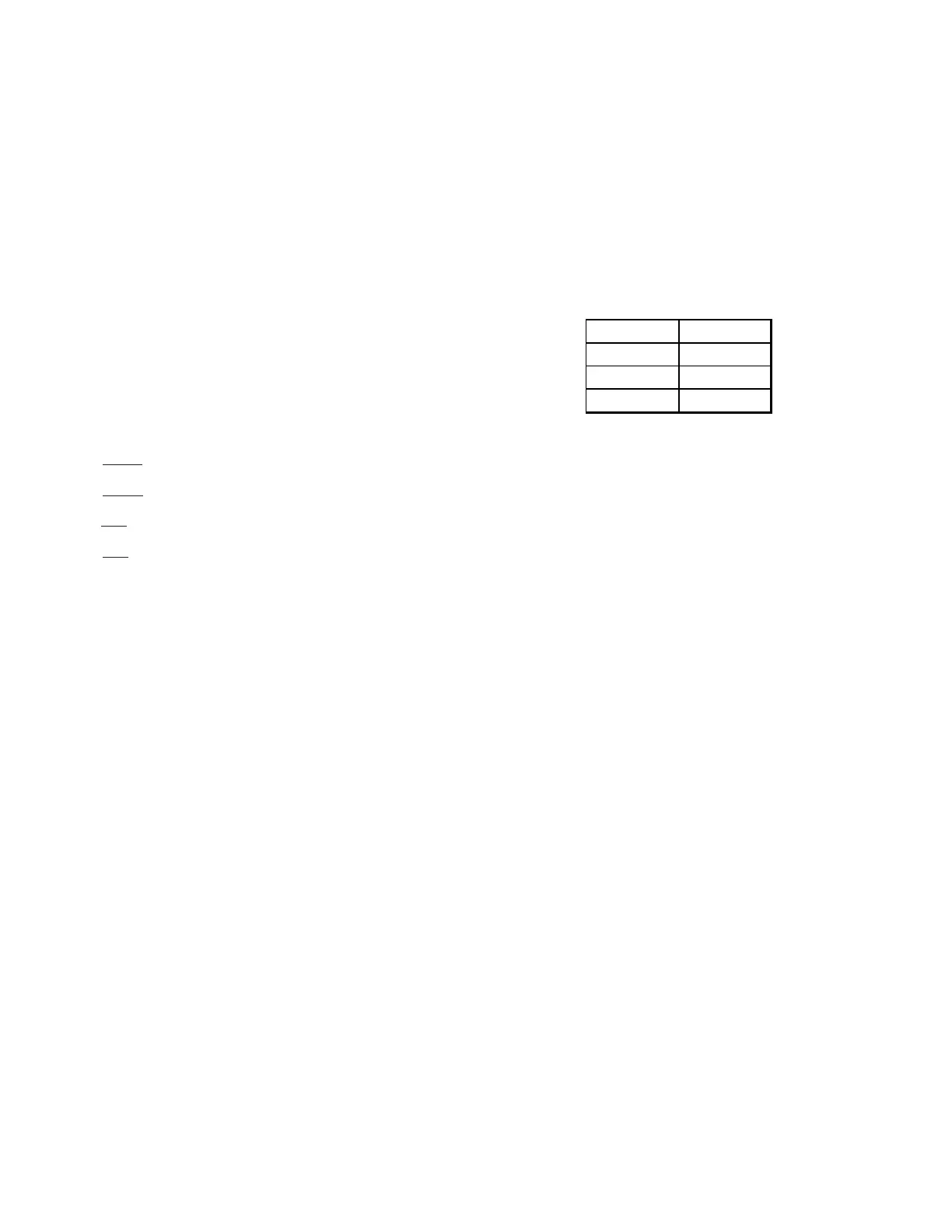
The difference is 11° subcooling. See the following table for the
design subcooling range for your unit.
2 TON 10-12°F
3 TON 13-15°F
4 TON 8-10°F
5 TON 11-13°F
There are other causes for high head pressure which may be found
in the "Cooling/Heating Analysis Chart."
If other causes check out normal, an overcharge or a system con-
taining non-condensables would be indicated.
If this system is observed:
1. Start the system.
2. Remove and capture small quantities of gas from the suction
line dill valve until the head pressure is reduced to normal.
3. Observe the system while running a cooling performance test.
If a shortage of refrigerant is indicated, then the system con-
tains non-condensables.
SUBCOOLING ADJUSTMENT ON EEV APPLICATIONS
NOTE: Subcooling information is valid only while the unit is
operating at 100% capacity or 100% compressor speed in CHARGE
MODE.
Compressor speed is displayed under STATUS menu in the
thermostat.
1. Run system at least 20 minutes to allow pressure to
stabilize. During the adjustment of subcooling, ambient
temperature should be greater than 65°F and less than
105°F. If ambient temperature is out of range, don’t adjust
subcooling.
2. For best results, temporarily install a thermometer on the
liquid line at the liquid line service valve. Ensure the
thermometer makes adequate contact and is insulated for
best possible readings. Use liquid line temperature to
determine sub-cooling.
3. The system subcooling should fall in the range shown in
following table. If not in that range, adjust subcooling
according to the following procedure.
a. If subcooling is low, add charge to adjust the subcooling
as specified in the following table.
 Loading...