76 Rev. 2
SERVICING
To aid in identifying these controls, color coded labels are
attached to the back of the controls. Refer to the chart be-
low for color codes and temperature settings.
Part Number 06 16
Open Setting (°F) 160° 150°
Color Orange Red
GUI_045 A,B,C,D
GUI_070 A,B,C,D S,V
GUI_090 A,B,C,D S,V
GUI_115 A,B,C,D,S,V
GUI_140 A,B,C,D,S,V
GCI_045 A,B,C
GCI_070 A,B,C,S
GCI_090 A,B,C,S
GCI_115 A,B,C
GCI_140 A,B,C
AUXILLARY LIMIT SWITCHES (101235_ _)
S-7 CHECKING FLAME ROLLOUT SWITCH
A temperature activated manual reset control is mounted to
the manifold assembly, as shown in the following drawing.
The control is designed to open should a flame roll out oc-
cur. An over firing condition or flame impingement on the
heat shield may also cause the control to open. If the rollout
control opens, the air circulation blower and vent blower will
run continuously. On models with the WR50A50, WR50A51
and HSI 1-1A ignition controls the diagnostic light will flash
four times. These symptoms are identical to a trip of the
primary limit control. On models with the HSI-2 ignition con-
trol the diagnostic light will flash five times indicating a trip of
the rollout switch.
To aid in identifying these controls, color coded labels have
been affixed to the back of these controls. Refer to the chart
below for temperature settings and color codes.
Part Number 08 09 10 11 12 13
Open Setting 260 275 300 250 325 350
Color
BROWN PINK LT GREEN LT BLUE LT PURPLE GRAY
GUI_045 A,B C, D
GUI_070 V A,B,C,D
GUI_090 D A,B,C,V
GUI_115 D V A,B,C
GUI_140 A,B C,V
GCI_045 A,B,C
GCI_070 A,B,C
GCI_090 A,B,C
GCI_115 A,B,C
GCI_140 A,B,C
ROLLOUT LIMIT SWITCHES (101235_ _)
If the rollout control has opened the circuit between the igni-
tion control and gas valve will be interrupted. The ignition will
cycle and try to light 3 times but will not sense flame and go
into lockout.
WARNING
LINE VOLTAGE NOW PRESENT.
1. Remove the burner compartment door to gain access to
the rollout switch(es) mounted to burner bracket.
The servicer should reset the ignition control by opening and
closing the thermostat circuit. Then look for the ignitor glow-
ing which indicates there is power to the ignition control.
Measure the voltage between each side of the rollout control
and ground while the ignition control is try to power the gas
valve.
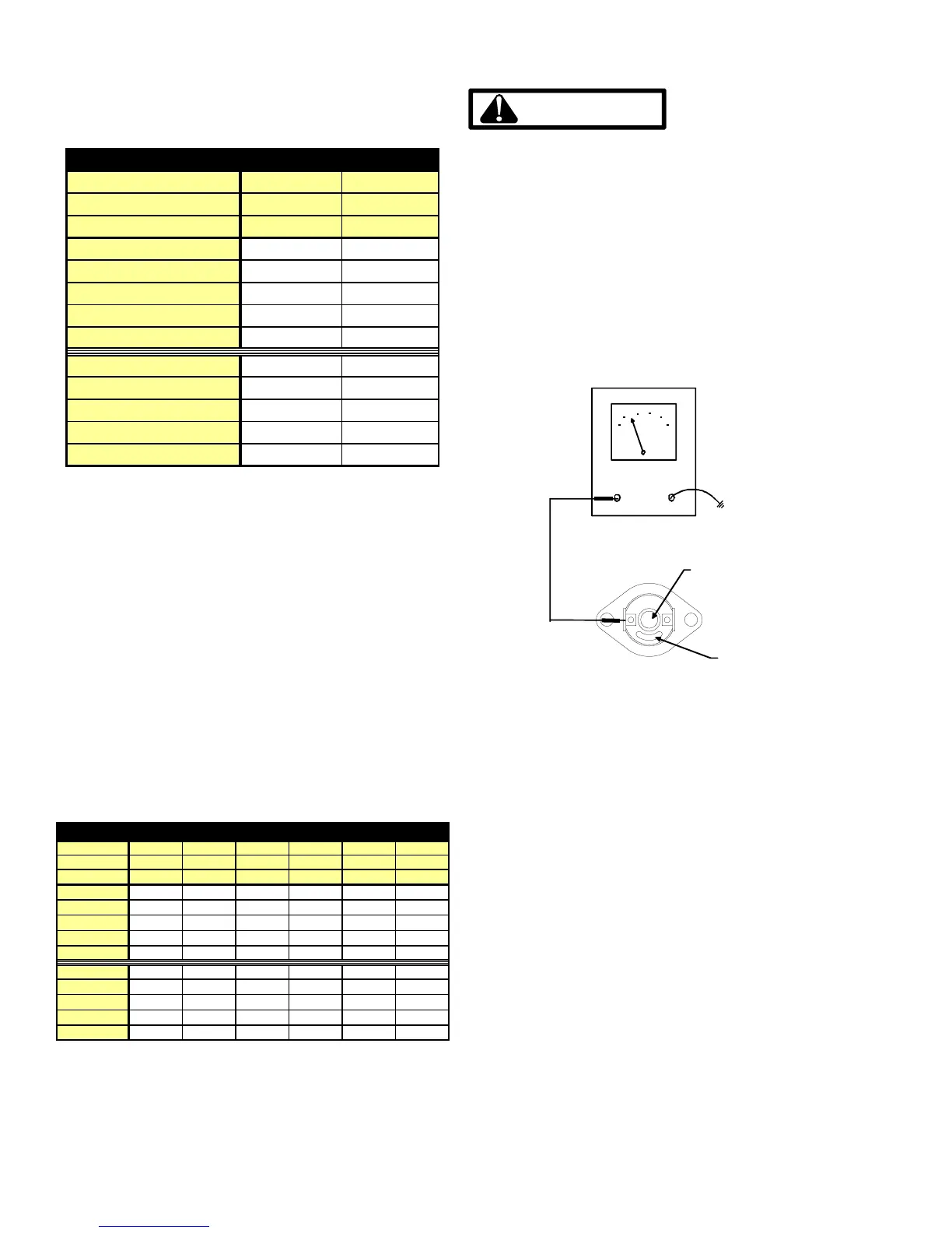
2. Measure the voltage between each side of the rollout
control and ground during the ignition attempt. Refer to
the following figure.
Color
Identifing
Tab
Red
Reset
Button
VOLT / OHM
METER
GND
Checking Flame Rollout Switch
a. If no voltage is measured on either side of control it indi-
cates ignition control or wiring to control problem.
b. If voltage is measured on one side of the control and not
the other it indicates the control is open.
c. If voltage is measured on both sides of the control the
wiring to gas valve or valve is a fault.
3. After check and/or replacement of rollout switch, rein-
stall burner compartment door and verify proper unit op-
eration.
S-8 CHECKING PRESSURE SWITCH
A pressure control device is used to measure negative pres-
sure at the induced draft blower motor inlet to detect a par-
tial or blocked flue.
The pressure control is a safety device to prevent the com-
bustion cycle from occurring with inadequate venting caused
by a restricted or blocked vent pipe.
 Loading...