22
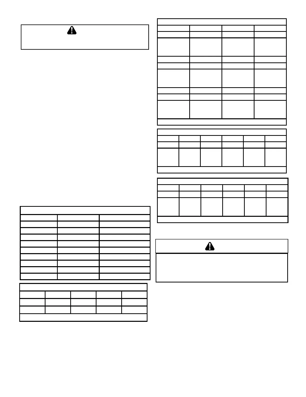
1 2 3 1 2 3
Position
OFF OFF OFF ON OFF OFF
Motor Speed
COOL
Y T1 T2
1 2 3 1 2 3 *1 2 3
ON ON OFF OFF ON OFF OFF OFF ON
Motor Speed
COOL
T3 T4 T1+T2
1 2 3 1 2 3 1 2 3
OFF ON ON ON OFF ON ON ON ON
Motor Speed
COOL
T1 T1 T1
COOL MOTOR SPEED DIP SWITCH SETTING (S1-1, S1-2, S1-3)
* = DEFAULT SETTING
1 2 *1 2 1 2 1 2
Position OFF OFF ON OFF ON ON OFF ON
Motor
Speed
HEAT
W T1 T2 T3 T4
HEAT MOTOR SPEED DIP SWITCH SETTING (S2-1, S2-2)
* = DEFAULT SETTING
*3 4 3 4 3 4 3 4
Position OFF OFF ON OFF OFF ON ON ON
Motor
Speed
FAN
G T1 T2 T4 T1+T2
FAN MOTOR SPEED DIP SWITCH SETTING (S2-3, S2-4)
* = DEFAULT SETTING
WARNING
T
O AVOID PERSONAL INJURY OR DEATH, DO NOT REMOVE ANY INTERNAL
COMPARTMENT COVERS OR ATTEMPT ANY ADJUSTMENT.
E
LECTRICAL
COMPONENTS ARE CONTAINED IN BOTH COMPARTMENTS.
C
ONTACT A
QUALIFIED SERVICE AGENT AT ONCE IF AN ABNORMAL FLAME APPEARANCE
SHOULD DEVELOP.
Refer to your furnace rating plate for the maximum ESP (ex-
ternal duct static) rating.
Total external static refers to everything external to the furnace
be considered when reading your total external static pres-
sure. The supply duct pressure must be read between the
furnace and the cooling coil. This reading is usually taken by
Take a duct static reading at the test hole. Tape up the test
hole after your test is complete. The negative pressure must
T
O
AVOID
PERSONAL
INJURY
OR
DEATH
DUE
TO
ELECTRICAL
SHOCK
,
TURN
OFF
POWER
TO
THE
FURNACE
BEFORE
CHANGING
SPEED
TAPS
.
WARNING
Furnaces are equipped with a EEM circulator blower motor.
This provides ease in adjusting blower speeds. Refer to the
Blower Performance Data in the back of the manual for proper
selection of heating and cooling speeds.
To adjust the circulator blower speed, proceed as follows:
1. Motor speed Tap wiring must remain in factory position
on the control board and motor
2. There are 4 speed Tap wires to the motor T1, T2, T3,
T4.)
3. There are 5 speeds available, depending on DIP switch
furnace.
4. Cooling speed can be adjusted by adjusting S1-1, S1-2,
5. Heating speed can be adjusted by adjusting S2-1, S2-2
6. Circulation / Continuous Fan speed can be adjusted by
7. Verify Proper temperature rise as outlined in the
Temperature Rise section of Startup Procedure and
Adjustment. Please refer to the tables below for dip
switch settings.
CONNECTOR ID DESCRIPTION CONNECTOR VOLTAGE
L LINE, L1 LINE, L1
G GROUND CHASSIS GROUND
N LINE, L2 LINE, L2
C SIGNAL COMMON 24VAC COMMON
1 TAP 1 24VAC
2 TAP 2 24VAC
3 TAP 3 24VAC
4 TAP 4 24VAC
5 TAP 5 24VAC
Motor Tap Identification
S1-4 Min Nom Max Units
ON
*150
Seconds
OFF 100 Seconds
Heat Off Delay (S1-4)
* = DEFAULT SETTING



 To Next Page