21
1
2
C
R
C
G
Y
Optional
Optional
Optional
INDOOR
BOARD TERMINAL
CONNECTIONS
OUTDOOR
BOARD TERMINAL
CONNECTIONS
1
2
C
R
C
G
Y
24 VA C
Thermostat
Communicating Inverter Air Conditioner or Heat Pump
Figure 20
3) Download the Cool Cloud HVAC phone application
for charging and to congure/test system operations.
NOTE: When new versions of Bluetooth Communication
Software and Furnace Control Software are available, the
phone application noties the user. Software updates are
classied as either optional or mandatory and installed by
using the phone application. Ensure all mandatory software
updates have been installed. Review notes for optional
software updates and install if necessary.
NOTE: If an E11 code exists for the inverter system immediately
after line voltage is applied (code shown in the Cool Cloud
HVAC phone application or displayed on the inverter control),
the System Verication Test needs to be completed before any
other operation. See the following procedure.
1) Allow the system to remain Idle for 5 minutes.
2) Turn the system verication test on either by using
the phone application, or by entering the menu
through the furnace push buttons.
3) Wait for the test to complete.
Charging
1) Inverter units using the Cool Cloud HVAC phone
application or control board push button:
a. Inverter units are charged by setting the
menu (Charge Mode) to ON through the
furnace control board push buttons or through
the Cool Cloud HVAC phone application.
b. The System will remain in charge mode (high
speed) for 60 minutes before timing out.
c. The installer must manually shut off charge
mode once complete.
2) Two-stage outdoor units using the Cool Cloud HVAC
application:
a. Using the cooling icon after entering the
outdoor unit menus, energize the outdoor unit
at 100% capacity.
b. Charge the outdoor unit as required using the
charging information provided with the outdoor
equipment.
Gas Furnace Testing
1) Two-stage Operation using the Cool Cloud HVAC
application:
a. Select the gas heat icon after entering the
furnace menus.
b. Select any value less than 50% for low stage
operation and any value greater than 50% for
high stage operation.
4) Conrm thermostat heating and cooling calls function
proprly with equipment.
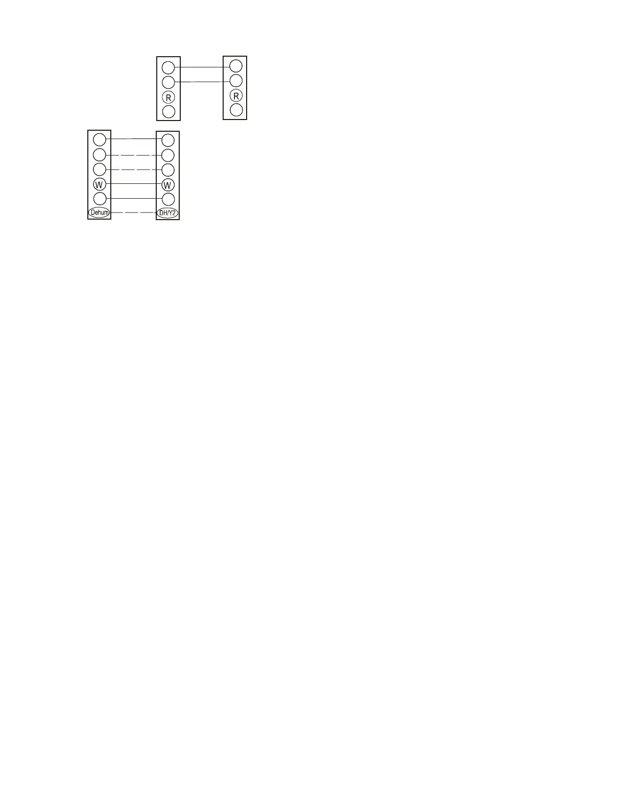
quiCk StArt guiide for non-CommuniCAting out-
door unitS
EXTREMELY IMPORTANT: For two-stage gas heating, the
system only needs a single W input. Internal algorithms will
control staging of the gas furnace automatically based on the
single W input. For non-communicating outdoor unit wiring
see instructions below.
1) Use the wiring diagrams below to connect low voltage
thermostat wires.
NOTE: When installing the furnace with a non communicating
heat pump wire directly from the “O” terminal on the thermostat
to the reversing valve “O” terminal on the non communicating
heat pump. See Figure 23 for single stage and Figure 24 for
the two stage diagrams.
 Loading...