11
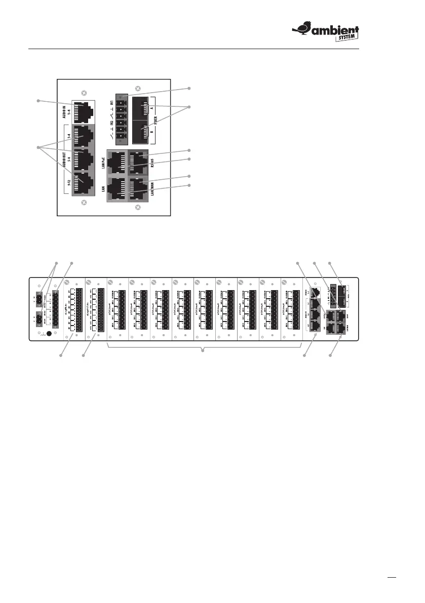
Fig. 6.
1
2
3
5
6
7
8
Diagram of dedicated communication card of ABT-CU-11LT / ABT-CU-11LCD control unit
Fig. 7.
Rear panel of ABT-CU-11LT / ABT-CU-11LCD – example of extension card arrangement
1. Power supply 48V DC
2. Connector for 100V amplier outputs to supply internal BUS available to all control cards
3. RJ-45 connectors, LAN with PoE, 2 items
4. RJ-45 connector – RS485 signal
5. Optical ber connectors. Marked as A, B
c
An optical ber connector is equipped with laser. Be particularly careful and avoid eye
contact with laser beam.
6. RJ-45 connectors, WAN
7. ABT-xCPU-AudIO-4/12 card; 4 audio input channels (upper port) are white, while 12 audio
outputs (3 lower ports) – grey
8. ABT-xCtrLine-4 control cards
9. ABT-xLogOUT-8c logic output card
10. ABT-xLogIN-8c logic input card
c
ABT-CU-11LT control unit has integrated communication card and audio input / output card.
1. Audio input
2. Audio outputs
3. Logic inputs/outputs
4. Optical ber connectors
5. RS485 communication port
6. LAN PoE port
7. LAN/WAN port
8. LAN port
 Loading...