EasyManua.ls Logo

American Standard 2/4TEC3F18A1000A User Manual

American Standard 2/4TEC3F18A1000A
12 pages
To Next Page IconTo Next Page
Page #1 background imageLoading...
Page #1 background image
ALL phases of this installation must comply with NATIONAL, STATE AND LOCAL CODES
IMPORTANT This Document is customer property and is to remain with this unit. Please return to service information
pack upon completion of work.
HAZARDOUS VOLTAGE - DISCONNECT POWER BEFORE SERVICING
WARNING:
Installer’s Guide
General Information 1
Installation Limitations & Recommendations 1-3
Unit Installation 3-4
Upflow 3
Downflow 3-4
Horizontal Left 4
Horizontal Right 4
Duct Connections 5
Refrigerant Piping 5
Condensate Drain Piping 5-6
Electrical — Power Wiring 6
Control Wiring 7
Checkout Procedure 11-12
Hook-up Diagrams 7-8
Outline Drawings 9-10
Contents
A. GENERAL INFORMATION
WARNING
!
THIS INFORMATION IS FOR USE BY INDIVIDUALS
HAVING ADEQUATE BACKGROUNDS OF ELECTRICAL
AND MECHANICAL EXPERIENCE. ANY ATTEMPT TO
REPAIR A CENTRAL AIR CONDITIONING PRODUCT
MAY RESULT IN PERSONAL INJURY AND/OR PROP-
ERTY DAMAGE. THE MANUFACTURER OR SELLER
CANNOT BE RESPONSIBLE FOR THE INTERPRETATION
OF THIS INFORMATION, NOR CAN IT ASSUME ANY
LIABILITY IN CONNECTION WITH ITS USE.
CAUTION
!
To prevent shortening its service life, the air handler
should not be used during the finishing phases of
construction. The low return air temperatures can lead
to the formation of condensate. Condensate in the
presence of chlorides and fluorides from paint, varnish,
stains, adhesives, cleaning compounds, and cement
creates a corrosive condition which may cause rapid
deterioration of the cabinet and internal components.
These instructions do not cover all variations in systems or
provide for every possible contingency. Should further
information be desired or particular problems arise which
are not covered sufficiently by this manual, contact your
local distributor or the manufacturer as listed on the air
handler nameplate.
These Air Handlers are shipped from the factory in the
upflow or horizontal right configuration and are fully
convertible to downflow or horizontal left. Refer to
Section B beginning on page 3 for additional information.
INSPECTION
Check carefully for any shipping damage. This must be
reported to and claims made against the transportation
company immediately. Check to be sure all major
components are in the unit. Any missing parts should
be reported to your supplier at once, and replaced with
authorized parts only.
CAUTION
!
Cardboard packing material must be removed from inside
the blower assembly before starting the unit. Failure to do
so may cause indoor blower motor failure.
INSTALLATION LIMITATIONS & RECOMMENDATIONS
The general location of the air handler is normally
selected by the architect, contractor and/or home owner for
the most effective application and satisfaction.
These air handlers are suitable for installation in a closet,
alcove or utility room with free, non-ducted, air return,
using the area space as a return air plenum. With ducted
supply air, if the minimum clearances to combustible
materials and service access are observed, the above
installations are suitable.
18-GE08D1-2
Convertible Air Handlers
1-1/2 – 5 Ton
2/4TEC3F18A1000A 2/4TEC3F42A1000A
2/4TEC3F24A1000A 2/4TEC3F48A1000A
2/4TEC3F30A1000A 2/4TEC3F55A1000A
2/4TEC3F36A1000A 2/4TEC3F60A1000A
Question and Answer IconNeed help?

Do you have a question about the American Standard 2/4TEC3F18A1000A and is the answer not in the manual?

American Standard 2/4TEC3F18A1000A Specifications

General IconGeneral
BrandAmerican Standard
Model2/4TEC3F18A1000A
CategoryAir Handlers
LanguageEnglish

Summary

General Information

Installation Limitations and Recommendations

Details site selection, clearances, and specific installation constraints for optimal system performance and safety.

Unit Installation

Upflow Installation

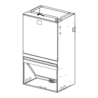
Instructions for configuring the air handler for upflow airflow and positioning.

Downflow Installation

Steps for converting the air handler to a downflow configuration, including baffle changes.

Horizontal Left Installation

Procedures for setting up the unit for horizontal left airflow and necessary modifications.

Horizontal Right Installation

Details on the factory configuration for horizontal right airflow and any required adjustments.

Duct Connections

Refrigerant Piping

Condensate Drain Piping

Electrical Wiring

Power Wiring

Information on power supply voltage, wire sizing, fuse selection, and connections.

Control Wiring

Details on low-voltage wiring for thermostat, outdoor unit, and system control connections.

Outline Drawings

Cage Nut Mounting Instruction

Checkout Procedure

Supplementary Heaters Checkout Procedures

Specific checks required for air handlers equipped with supplementary electric heaters.
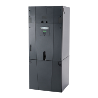
Related product manuals