EasyManua.ls Logo

American Standard TMM5A0B30M21SAA - User Manual

American Standard TMM5A0B30M21SAA
12 pages
Print Icon
To Next Page IconTo Next Page
Loading...
WALL-MOUNT AIR HANDLERS
2-3TON COOLING/HEAT PUMP
18-GF06D1-1
TMM5A0B24M21SAA
TMM5A0B30M21SAA
TMM5A0B36M31SAA
ALL phases of this installation must comply with NATIONAL, STATE AND LOCAL CODES
Important: This Document is customer property and is to remain with this unit.
Installer’s Guide
Section 1. Features
1.1 Standard Features
FRONT OR BOTTOM RETURN AIR.
PAINTED FINISH ON GALVANIZED STEEL
STURDY POLYCARBONATE DRAIN PANS
- The TMM5A wall mount air handler has factory
installed drain pans and is shipped for upflow
applications only.
208/230 VAC OPERATION
MULTI-SPEED DIRECT DRIVE BLOWER
CONSTANT TORQUE ECM MOTOR WITH
FAN-OFF TIME DELAY PROGRAMMING
FACTORY INSTALLED R-410A THERMAL
EXPANSION VALVE
1.2 Optional Accessories
5, 7.5 and 10 kW SINGLE PHASE ELECTRIC
HEATERS
- Circuit breakers are standard on all single
phase 5,
7.5 and 10 kW heaters.
The TMM5A series wall mount air handler is designed for installation in a closet, utility room, alcove
and can be wall mounted. These versatile units are applicable to air conditioning and heat pump
applications. Field installed electric resistance heaters are available.
STUD OR WALL MOUNTING TABS
FULLY INSULATED CABINET
3/4'' NPT PRIMARY AND SECONDARY DRAINS
7)0575$16)250(5
)/)86(/,1.
)0)$102725
&$3 )$1 &$3$&,725
*1' *5281'
),(/' 32:(5 :,5,1*
*1'
9
&20
9
9
7)05
FM
%51&
%/8
<**1'
:+,7(
<(/1
%/./
NOTES:
1: Use Copper Wire (75 Min) Only Between Disconnect Swicth And Unit .
2: To Be Wired In Accordance With NEC And Local Codes.
3: If Any Of The Original Wire ,As Supplied,Must Be Replaced.Use The Same
Or Equivalent Type Wire.
4: Connect R To R,G To G,Etc.See Outdoor Instruction For Details.
5: To Change Speed Tap,Move Blue Wire Desird Terminal.
6: See Airflow Tables For Tap Usage.
7:Factory Wires May Be Present,DO NOT USE.
ć
7)0575$16)250(5
)/)86(/,1.
)0)$102725
*1'
&20
9
9
7)05
NOTES:
1: Use Copper Wire (75 Min) Only Between Disconnect Swicth And Unit .
2: To Be Wired In Accordance With NEC And Local Codes.
3: If Any Of The Original Wire ,As Supplied,Must Be Replaced.Use The Same
Or Equivalent Type Wire.
4: Connect R To R,G To G,Etc.See Outdoor Instruction For Details.
5: To Change Speed Tap,Move Green Wire Desird Terminal.
6: See Airflow Tables For Tap Usage.
ć
FM
<**1'
1
&
/
Question and Answer IconNeed help?

Do you have a question about the American Standard TMM5A0B30M21SAA and is the answer not in the manual?

Summary

Section 1. Features

1.1 Standard Features

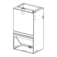
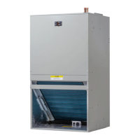
Lists the standard features of the wall-mount air handler unit.

1.2 Optional Accessories

Details optional accessories available for the air handler unit.

Section 2. Safety Information

General Safety Warnings

Covers critical safety warnings for installation and servicing.

Material Hazards and Precautions

Addresses hazards related to fiberglass insulation and necessary precautions.

Operational Safety Checks

Highlights essential checks before operating the unit, like blower motor security.

Section 3. Installation Instructions

3.1 Unpacking and Location

Covers unpacking, inspection, and selecting the installation location.

3.2 Mounting Options

Details the procedures for wall mount and frame mount installations.

3.3 Duct Work

Guidelines for properly installing ductwork for airflow and compliance.

3.4 Condensate Drain

Procedures for correctly installing condensate drain lines for proper drainage.

3.5 System Connections

Covers refrigerant piping, metering device, blower, filter, and thermostat.

3.8 Wiring

Comprehensive instructions for power, control, and grounding wiring.

3.11 Sequence of Operation

Explains the operational sequences for cooling and heating modes.

3.12 Operational and Checkout Procedures

Steps for checking and verifying proper system operation after installation.

3.13 Maintenance

Recommendations for routine maintenance to ensure optimal performance.

Section 4. Wiring

HEAT PUMP SYSTEMS Wiring

Wiring diagram and connections for heat pump system configurations.

AC SYSTEMS Wiring

Wiring diagram and connections for standard AC system configurations.

Section 5. Heater Pressure Drop Table

Section 6. Performance and Electrical Data

Section 7. Dimensional Data

7.1 UNIT DIMENSIONS

Provides detailed physical dimensions and weight specifications for the unit.

American Standard TMM5A0B30M21SAA Specifications

General IconGeneral
BrandAmerican Standard
ModelTMM5A0B30M21SAA
CategoryAir Handlers
Nominal Cooling Capacity2.5 Tons
Voltage208/230 V
Phase1
RefrigerantR-410A
Air Flow Range800-1200 CFM
Depth21 inches
Width21 inches

Related product manuals