Do you have a question about the American Standard TAM9A0A24V21DA and is the answer not in the manual?
Warning about electrical hazards and potential for injury or death.
Importance of inspecting and using proper service tools for grounding.
Caution when working with live electrical components during service.
Warning about hazards associated with pressurized refrigerant and oil.
Caution regarding sharp edges on equipment during installation or servicing.
Information about chemical exposure risks known to cause cancer or birth defects.
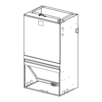
Guidelines on where to screw or puncture the unit cabinet during installation.
Instructions for removing the four access panels on the air handler unit.
Guidance for installing air handlers without a return duct in closets or utility rooms.
Recommendations for installing air handlers with ducted supply and return air.
Instructions and considerations for setting up the unit for upflow airflow.
Steps for assembling the plenum using the manufacturer's guide.
Requirements and procedures for downflow installation of the unit.
Procedures for connecting low voltage wiring to the air handler unit.
Specific instructions for control board orientation in horizontal right configurations.
Overview of the system status display and fault information on the home screen.
Instructions for accessing and navigating technician menus and screens.
Diagram of the technician menu structure for the home screen display.
Details on monitoring system parameters and data within the technician menu.
Information on viewing active and historical faults and their descriptions.
Options for configuring system parameters like airflow, heating type, and fan settings.
Procedures for initiating unit tests and controlling CFM and EEV.
Details on Continuous Fan, Cooling, Heat Pump, Electric, and Hydronic heating operations.
Procedures for defrost initiation and system response to freeze conditions.
Procedure for entering and executing the unit's test mode.
Methods for clearing active and historical fault codes from the control board.
| Model Number | TAM9A0A24V21DA |
|---|---|
| Product Category | Air Handlers |
| Brand | American Standard |
| Voltage | 208/230V |
| Phase | 1 |
| Frequency | 60 Hz |
| Refrigerant | R-410A |
| Cooling Capacity | 24000 BTU |
| Heating Capacity | 24000 BTU |
| Motor Type | Variable Speed |