Do you have a question about the American Standard 2TEE3D37A1000A and is the answer not in the manual?
Mandatory safety warning regarding high voltage before servicing the unit.
Information for individuals with adequate electrical and mechanical experience for repairs.
Preventing condensate damage to internal components during construction finishing.
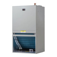
Instructions for checking for shipping damage and verifying all major components.
Note on potential condensation on air handler surfaces in unconditioned locations.
Description of the Field Charger's role in charging contaminants.
Description of the Collection Cell's function in removing impurities.
Details on the power supply converting voltage for cleaner components.
Explanation of the safety switch cutting power to cleaner components.
Detailed procedure for taking apart and reassembling the unit's two-piece cabinet.
Initial steps and cautions for upflow unit installation.
Specific procedures for upflow installation, including baffle and drip tray.
Initial steps and cautions for downflow unit installation.
Specific procedures for downflow installation, including baffle kit.
Instructions for installing the downflow baffle kit and related components.
Guidelines for correctly positioning and supporting the air handler unit.
Requirement for a subbase when installing supplementary heaters in downflow.
Specifications for return plenum dimensions and connections.
Details on flanging and securing sheetmetal return plenums.
Installing the Field Charger and Collection Cell in downflow configuration.
Initial steps and cautions for horizontal left unit installation.
Specific procedures for horizontal left installation, including coil rotation.
Recommendation for installing an auxiliary drain pan under horizontal air handlers.
Initial steps and cautions for horizontal right unit installation.
Specific procedures for horizontal right installation, including support.
Installing the Field Charger and Collection Cell in horizontal right.
Diagrams showing correct placement of components in upflow configuration.
Diagrams showing correct placement of components in downflow configuration.
Diagrams showing correct placement of components in horizontal left configuration.
Diagrams showing correct placement of components in horizontal right configuration.
Guidance on using convertible duct flanges and sealing connections.
Requirements for flanging sheetmetal return plenums for proper connection.
Importance of routing refrigerant lines to ensure access to components.
Procedure to protect the TXV sensing bulb from overheating during brazing.
Instructions for using the provided brazing shield to protect painted areas.
Steps for connecting and brazing refrigerant lines to the indoor coil.
Specifications for primary drain trap type, location, and clean-out.
Guidance on connecting secondary drains and sealing weep holes.
Recommendations for drain line slope, insulation, and freeze prevention.
Recommendation for installing an auxiliary drain pan under horizontal air handlers.
Details on voltage selection, wire sizes, and fuse requirements.
Low voltage wiring between units, comfort control, and supplementary heaters.
Adjusting blower speed using the ECM fan control and dip switches.
Using the blower performance table to set correct airflow for tonnage.
Configuration of the fan off-delay settings via dip switches.
Addressing potential sounds from the air cleaner and power setting adjustment.
Guidance on the recommended inspection and cleaning intervals for the Collection Cell.
Procedure for cleaning the Collection Cell using vacuuming.
Procedure for cleaning the Collection Cell by washing with water.
Instructions for properly drying and reinstalling the Collection Cell.
Safety warnings regarding sharp pins and wearing protective gloves.
Method for cleaning the Field Charger faceplate and pins.
Wiring diagram for single stage cooling and two stage heat systems.
Wiring diagram for two stage cooling and two stage heat systems.
Wiring diagram for single stage heat pump systems.
Table detailing minimum clearances to combustible materials and for service.
Table listing dimensions (A-K) for various unit models.
Overall height (H) and width (W) dimensions for unit models.
Steps to ensure power is off and disconnect switch is locked before servicing.
Verification of wiring, ductwork, drain lines, and system operation.
Specific checkout procedures for units equipped with supplementary heaters.
| Model Number | 2TEE3D37A1000A |
|---|---|
| Category | Air Handlers |
| Brand | American Standard |
| Voltage | 208/230V |
| Phase | 1 |
| Refrigerant | R-410A |
| Air Flow | 1200 CFM |
| Motor Type | Multi-speed |
| Width | 21 inches |
| Depth | 21 inches |
| Weight | 130 lbs |
| Cooling Capacity | 3 Ton |
| Filter Type | Standard |