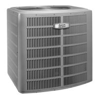
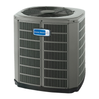
The document is an application guide for American Standard Allegiance and Heritage 18 dual compressor cooling units and heat pumps. It provides comprehensive information regarding the installation, operation, and maintenance of these HVAC systems, particularly focusing on aspects related to their application in various environmental and spatial conditions.
Function Description
The American Standard Allegiance and Heritage 18 units are designed for both cooling and heating applications, utilizing a dual compressor system. These units are capable of operating in cooling mode down to 45°F as shipped from the factory. For lower outdoor operating temperatures, specific accessories are required to ensure proper functionality. The units are intended to be matched with variable speed air handling units or variable speed furnace/coil combinations, which are equipped with factory-supplied non-bleed TXVs. The dual compressor design suggests a staged operation, where compressors do not operate simultaneously, optimizing efficiency and performance across different load conditions. The guide details the necessary controls and components for extended low-temperature operation, such as Evaporator Defrost Control Kits (EDC) for cooling-only and heat pump models, and notes that Compressor Crankcase Heater Kits and Compressor Hard Start Kits are factory supplied.
Usage Features
The guide outlines several key usage features and considerations for these units:
- Low Outdoor Operating Temperature: The units can operate in cooling mode down to 45°F without additional accessories. For operation between 30°F and 40°F, an Evaporator Defrost Control Kit (EDC) is required. Operation at 0°F is not approved. This feature allows for cooling in milder winter conditions or specific industrial applications where cooling is needed year-round.
- Unit Mounting: Detailed instructions are provided for mounting the units, emphasizing the importance of proper support and stability. If the unit is supported from the edge, the supporting material must extend at least two inches under the perimeter of the base. Mounting holes are molded into the basepan but require drilling. Washers are recommended between the fastener head and the basepan. American Standard suggests supporting the center of the unit. For regions with seismic loads or high winds, specific extreme conditions mounting kits and installation instructions should be consulted.
- Minimum Operating Clearances: This section is crucial for ensuring optimal performance, serviceability, and compliance with codes. Adequate airflow is essential for heat transfer and maintaining head pressure within an effective operating range. Sufficient space is also required for HVAC service technicians to perform maintenance and component changes, adhering to National Electric Code (NEC) requirements. Space maintenance is also addressed to prevent debris accumulation that could obstruct airflow.
- Single Unit Installation (Corner with Unrestricted Top Clearance):
- Below 105°F ambient: 1.0 feet clearance on two sides, with 1.0 feet minimum clearance from shrubbery. Service access side requires 3 feet minimum.
- Above 105°F ambient: 1.5 feet clearance on two walls, with 1.0 feet minimum clearance from shrubbery. Service access side requires 3 feet minimum.
- If service panel faces a wall: NEC requires 3 feet minimum between unit and wall, potentially increasing to 3.5 feet.
- A minimum of 5 feet unrestricted top clearance is required.
- Multiple Unit Installation (Corner with Unrestricted Top Clearance):
- Below 105°F ambient: Corner unit needs 1.5 feet from side wall and 1.0 feet from back wall. 1 foot clearance between units (4 feet if service panels face each other per NEC).
- Above 105°F ambient: 2.0 feet clearance from both walls. 2 feet clearance between units (4 feet if service panels face each other per NEC).
- If service panels face a wall: NEC requires 3 feet minimum between unit and wall, potentially increasing to 3.5 feet.
- A minimum of 5 feet unrestricted top clearance is required.
- Single Unit Installation (Fenced Corner with Unrestricted Top Clearance):
- Below 105°F ambient: 1.0 feet clearance from both walls and 1.0 feet from fence. Fence openings must allow 300 FPM air velocity. Service access side requires 3.0 feet minimum.
- Above 105°F ambient: 1.5 feet clearance from both walls and 1.5 feet from fence. Fence openings must allow 300 FPM air velocity. Service access side requires 3.0 feet minimum.
- If service panel faces a wall: NEC requires 3 feet minimum between unit and wall, potentially increasing to 3.5 feet.
- A minimum of 5 feet unrestricted top clearance is required.
- Multiple Unit Installation (Fenced Corner with Unobstructed Top Clearance):
- Below 105°F ambient: Corner unit needs 1.5 feet from one wall and 1.0 feet from other wall. 1.5 feet clearance between units. NEC requires 3 feet for service (reducible to 2.0 feet if removable panels are used). Free air passage must be cut for 300 FPM air velocity.
- Above 105°F ambient: Corner unit needs 2.0 feet from one wall and 1.5 feet from other wall. 2.0 feet clearance between units. NEC requires 3 feet for service (reducible to 2.5 feet if removable panels are used).
- If service panels face a wall: NEC requires 3.0 feet minimum between unit and wall, potentially increasing to 3.5 feet.
- A minimum of 5 feet unrestricted top clearance is required.
- Single Unit Installation (Next to One Wall with Unrestricted Top Clearance):
- Below 105°F ambient: 6 inches clearance on one side, 3 feet on other three sides. If a fence/barrier is present, 3 feet clearance is required on three sides, and its height should not exceed the unit's height. Free air passage must be cut for 300 FPM air velocity. Service access side requires 3 feet minimum.
- If service panel faces a wall: NEC requires 3 feet minimum between unit and wall, potentially increasing to 3.5 feet.
- A minimum of 5 feet unrestricted top clearance is required.
- Multiple Units on Pad or Rooftop (Unobstructed Top Clearance):
- No cover should be constructed over units.
- NEC requires 3 feet minimum clearance between service access panel and adjacent unit (4 feet if certain conditions apply). If service access panel faces a wall, 3 feet minimum space is required (potentially 3.5 feet).
- Walls/fence height should not exceed the top of units.
- National, State, and Local Codes must be observed.
- Fence Construction: Fence height should not exceed the top of the unit. Free air passages, sized for no greater than 300 FPM velocity, should be cut in the lower portion of the fence. Undercutting the fence is permissible if grass, vegetation, or debris will not obstruct airflow. Shrubbery should not be planted within one foot of the fence. If removable panels are used, the distance from the unit's service panel to the removable panel can be reduced to 2.0 feet (3.0 feet if design outdoor dry bulb is greater than 105°F).
- Windshields: For low ambient operation (30°F or lower), windshields may be necessary to prevent prevailing winds from negatively impacting system performance. Designs for highly directional and non-directional winds are provided, emphasizing the need for service access areas and minimum clearances.
- Refrigerant Piping Limitations: The guide specifies strict limitations on refrigerant line lengths to ensure proper operation, especially given the dual compressor design where compressors do not operate simultaneously.
- Total line length: Not to exceed 80 feet.
- Vertical line length: Up to 25 feet of the total 80 feet.
- These limitations are critical because exceeding them can prevent liquid subcooling on the first stage and lead to insufficient oil return during first stage operation.
Maintenance Features
The document implicitly highlights several maintenance-related features and considerations:
- Service Access: The importance of providing sufficient access for maintenance and service is repeatedly emphasized throughout the clearance guidelines. The National Electric Code (NEC) dictates minimum working spaces to ensure technicians can safely and effectively maintain the equipment. This includes allowing space for major component change-outs.
- Space Maintenance: Adequate area around the units must be maintained to prevent debris, grass, and vegetation from collecting on panels and obstructing airflow. This ensures continuous optimal performance and reduces the need for frequent cleaning.
- Electrical Code Compliance: Adherence to local, state, and national electrical codes (specifically NEC Article 110.26) is mandatory for all HVAC installations. These codes define minimum working spaces around electrical equipment to ensure the safety of service personnel and proper maintenance. The guide provides excerpts from the NEC regarding working clearances based on voltage to ground and different conditions of exposed live parts.
- Product Data and Manuals: The guide frequently refers to other American Standard publications, such as the extreme conditions mounting kit installation instructions and the unit's product data manual, for the most current and detailed information. This ensures that technicians and installers have access to comprehensive resources for proper installation and maintenance procedures.
- Removable Panels: The mention of removable panels in fence construction and clearance guidelines suggests that the unit design or surrounding structures can incorporate features to facilitate easier access for service, potentially allowing for reduced service clearances in some cases.
In summary, the American Standard Allegiance and Heritage 18 application guide provides essential information for the proper selection, installation, and application of these dual compressor units, with a strong emphasis on ensuring optimal performance, safety, and ease of maintenance through detailed guidelines on operating conditions, mounting, clearances, and piping.