© 2009 American Standard Heating & Air Conditioning
Since the manufacturer has a policy of continuous product
and product data improvement, it reserves the right to
change design and specifications without notice.
11-AC18D1-4
These instructions do not cover all variations in systems
nor provide for every possible contingency to be met in
connection with installation. All phases of this installa-
tion must comply with NATIONAL, STATE AND LOCAL
CODES. Should further information be desired or should
particular problems arise which are not covered sufficiently for
the purchaser’s purposes, the matter should be referred to your
installing dealer or local distributor.
A. GENERAL
▲
WARNING:
This information is intended
for use by individuals possessing adequate backgrounds
of electrical and mechanical experience. Any attempt to
repair a central air conditioning product may result in
personal injury and or property damage. The manufac-
turer or seller cannot be responsible for the interpreta-
tion of this information, nor can it assume any liability in
connection with its use.
NOTE: AMERICAN STANDARD HEATING & AIR CONDI-
TIONING HAS ALWAYS RECOMMENDED INSTALLING
MANUFACTURER APPROVED MATCHED INDOOR AND
OUTDOOR SYSTEMS.
THE BENEFITS OF INSTALLING APPROVED MATCHED
SYSTEMS ARE MAXIMUM EFFICIENCY, OPTIMUM PER-
FORMANCE AND BEST OVERALL SYSTEM RELIABILITY.
Check for transportation damage after unit is uncrated. Report
promptly, to the carrier, any damage found to the unit.
To determine the electrical power requirements of the unit,
refer to the nameplate of the unit. The electrical power avail-
able must agree with that listed on the nameplate.
B. LOCATION AND PREPARATION OF THE UNIT
1. When removing unit from the pallet, notice the tabs on the
basepan. Remove tabs by cutting with a sharp tool as shown in
Figure 2 (see page 2).
2. The unit should be set on a level support pad at least as large
as the unit base pan, such as a concrete slab. If this is not the
application used please reference ALG-APG0*-EN (*latest revi-
sion number).
3. The support pad must NOT be in direct contact with any
structure. Unit must be positioned a minimum of 12" from any
wall or surrounding shrubbery to insure adequate airflow.
Clearance must be provided in front of control box (access panels)
& any other side requiring service access to meet National
Electrical Code. Also, the unit location must be far enough away
from any structure to prevent excess roof run-off water from
pouring directly on the unit. When choosing the location of the
unit(s), sound transmission through air and refrigerant lineset
should be taken into consideration. It is recommended to locate
unit(s) away from areas (bedrooms, etc.) where such sound could
be objectionable.
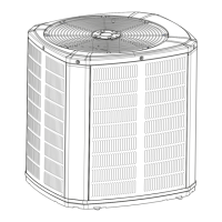
4. The top discharge area must be unrestricted for at least
five (5) feet above the unit.
5. When the outdoor unit is mounted on a roof, be sure the roof
will support the unit’s weight. Properly selected isolation is
recommended to prevent transmission to the building structure.
6. The maximum length of refrigerant lines from outdoor to
indoor unit should NOT exceed sixty (60) feet.
Condensing Units
INSTALLER'S GUIDE
ALL phases of this installation must comply with NATIONAL, STATE AND LOCAL CODES
5 FT. ABOVE UNIT — UNRESTRICTED
1
Models:
2A7A3018-060A
IMPORTANT — This Document is customer property and is to remain with this unit. Please return to service information pack
upon completion of work.