6
9
5
10
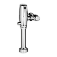
Fig. 8
121mm,+13mm, -6mm
(4-3/4)(+1/2, -1/4)
7
6
2
8
M965643 Rev. 1.6 (11/16)
5
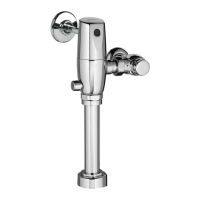
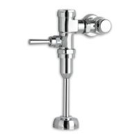
INSTALL FLUSH VALVE; Fig. 7
1. Insert the side ADJUSTABLE TAILPIECE (1) on the
FLUSH VALVE (2) into the STOP VALVE (3). Lubricate
the TAILPIECE O-RING (4) with water if necessary.
Thread the COUPLING NUT (5) onto the STOP VALVE
(3) and tighten lightly. Fig. 7.
Important: Do not use lubricants (other than water)
or any type of thread sealing paste or tape.
6
CONNECT FLUSH VALVE TO
VACUUM BREAKER TUBE; Fig. 8
1. Align the FLUSH VALVE BODY (2) (Fig. 9) directly
above the VACUUM BREAKER TUBE (7) and
VACUUM COUPLING NUT (6). Make sure that
GASKET (10) is installed.
Note: There is a +13mm, -6mm (+1/2"-1/4") tolerance
for the 121mm (4-3/4) dimension.
2. Pull the VACUUM BREAKER TUBE (7) up to meet the
threaded FLUSH VALVE CONNECTION (8) and hand
tighten the COUPLING NUT (6). Align all components
of the ush valve assembly.
3. Lightly tighten the TAILPIECE COUPLING NUT (5)
connection rst, then the VACUUM BREAKER
COUPLING NUT (6) and nally the SPUD COUPLING
NUT (9). Once alligned correctly, use a wrench to
tighten all couplings to make water tight connections.
4. Secure piping with in wall as required.
 Loading...