AL-800 Instruction Manual
3
Features
1. The AL-800 uses a rugged high-gain 3CX800A7 tube.
2. A time-delay circuit provides a 180 second warm-up to eliminate potential damage to the tube
cathode.
3. A grid overload circuit quickly disables the amplifier if the grid current becomes excessive.
This feature prevents excessive grid current from causing distortion or damaging the tube or
other components.
4. A thermal overload automatically disables the amplifier if excessive heating of the power
transformer occurs.
5. A dynamic bias circuit eliminates hundreds of watts of unnecessary heat generation in the
power amplifier tube. The result is cooler operation and longer component life.
6. A multi-voltage heavy-duty transformer with a unique "buck-boost" winding allows
adjustment of the primary voltage to 14 different voltages centered on 115 and 230 volts. This
versatile Ameritron feature allows the user to select the optimum primary voltage for maximum
performance and life.
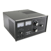
7. The tuning and loading controls have vernier 6:1 reduction drives for smooth tuning.
Logging scales allow quick and repeatable control adjustments for rapid band changes.
8. The AL-800 has two illuminated cross-needle panel meters. The left meter provides a
continuous reading of grid and plate currents. The right meter reads peak RF power output on
one scale and Plate Voltage (HV), Reflected power and SWR (REF), ALC detector voltage
(ALC), and ALC adjustment level (ALC SET) on the other scale.
9. Heater and plate voltages are maintained using the "STBY/OPR" switch. This allows the
amplifier to be conveniently bypassed for "barefoot" operation.
10. A front panel "ALC SET" control allows convenient adjustment of the ALC threshold. The
unique ALC circuit samples the grid current and power supply voltage.
11. "XMT" and "OL" LED's on the front panel indicate proper operation of the amplifier.
12. A rear panel 12 Volt auxiliary output jack provides up to 200 mA at 12 Vdc for accessories
such as the ATR-15 Antenna Tuner.
13. A step-start circuit limits the inrush current to the power supply and tube heater. This circuit
extends the life of the amplifier components.