FEATURES
1. Inexpensive tubes: the AL82 uses a pair of rugged 3-
500z tubes.
2. Fast warm-up time: the 3-500z requires only a few
seconds of warm-u
time.
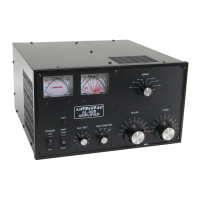
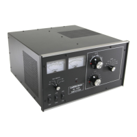
6. Two Illuminated Panel Meters: the AL-82 has two il-
luminated panel meters. The Grid Current meter provides
a continuous reading of grid current and indicates proper
operation of the amplifier. The other meter reads Plate
Voltage (HV), Plate Current (IP), Peak RF Watts (P O )
and ALC.
3. SSB/CW switch: the bias voltage is switched to provide
the best linearity on SSB or the lowest dissipation on
CW operation.
7. Operate/Standby Switch: filament and plate voltages are
maintained while allowing the amplifier to be bypassed
for "barefoot'' operation.
4. ALC Indicator: the drive level is detected to provide a
control voltage for the exciter. ALC prevents over-
driving of the linear and reduces distortion from ex-
cessive drive
ower.
8. 12 Volt Auxiliary Jack: 12 volts at 100 mA is provide for
accessories such as the ATR-15 Antenna tuner.
9. XMT Indicator LED: provides a front panel indication o
proper amplifier keying by the exciter during operation.
5. Vernler Plate and Load Adjustments: both tuning con-
trols have vernler 6:1 reduction drives for smooth
tunin
.
Caution: This amplifier must be disconnected from the
power mains before removing the cover. See the warning on
page 10.
ECHNICAL SPECIFICATIONS AL-82
Input
Circuit type: Pi-network, slug tuned coils
maximum VSWR at resonance: 1.2:1 minimum 2:1
VSWR bandwidth:
20% maximum drive power
permissible: 130 watts typical drive for full power
out
ut: 100 watts
Metering: multimeter: plate current, plate voltage,
drive/ALC,
ower out
ut
PEP watts
. Grid:
rid current
ALC: ne
ative
oin
0-20V
ad
ustable
hono
ack
Efficienc
CW: 65% t
ical
Output
circuit type: Pi-L, Pi
1
/2 hour continuous carrier: 1500 watts (Below 18mHZ)
30 second continuous carrier: 1800 watts plus
1
/2 hour PEP two-tone test: 1800 watts
30 second PEP two-tone test:1800 watts
lus
Efficiency SSB (envelope crest): 62% typical
MARSIWARC: yes,
andswitch set to nearest amateur band
Keying: requires relay closure or sinking to ground of
ositive
+
12 VDC at 100 mA
hono
ack
Power Supply
circuit type: full wave bridge, capacitor input no
load voltage: 3800V
full load voltage: 3300V full load current: .8 amp
regulation: 10% or better transformer: 32 lbs., hypersil
capacitors: 26 mfd total, computer grade maximum
draw at rated output: 13 amps at 240V AC -50/60 Hz
Tube
type (2) 3-500Z continuous dissipation: 1000
watts warm-up time: approximately 30
seconds
RF Connectors: S0239
Line Connector: NEMA 6-15P 240V st
le
Dimensions: 18
1/2" D x 17" W x 10"H
Wei
ht: 77 lbs.
Frequency Coverage: (AL-82)-1.8, 3.5, 7, 14, 18 and 21
MHz. User modified models cover 24 and 28 MHz. (AL-
82X/J)Export models-1.8, 3.5, 7, 14, 18, 21, 24 and 28
MHz.
Third Order IMD at Rated Output: -34 dB at 1500 w output