Do you have a question about the Ametek dunkermotoren BG 75x50 SI and is the answer not in the manual?
Essential safety instructions for commissioning, including disconnecting power and observing warnings.
Emphasizes proper transport and storage conditions, protecting the drive from dust, moisture, and shock.
Lists electrical specifications for the motor, including voltage, current, speed range, and protection limits.
Explains the ballast circuit function for storing braking energy and preventing overvoltage in the system.
Details the integrated temperature sensor that switches off the controller at 110°C to protect the motor.
Describes the I²t protective function that monitors and limits motor current to prevent overloading.
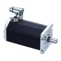
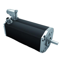
Provides instructions for mechanical mounting, fastening, and shaft load limits for the BG 75 SI motor.
Explains the importance of connecting the motor housing to earth for protection against static discharge (ESD).
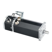
Details the 4-pin connector for motor power supply, including pin assignment, lead colours, and cautionary notes.
Provides a detailed pin assignment table for the 12-pole connector, mapping pins to functions and lead colours.
Provides essential safety instructions and initial steps for operating the motor, including power connection and control inputs.
Explains protection functions (over-temp, under-voltage) and how fault status is indicated via the OUT2 output.