Do you have a question about the Ametek dunkermotoren BG 75 SI Series and is the answer not in the manual?
Provides an overview of the SI drives, installation, and functional tests.
Defines key technical terms and concepts used throughout the manual.
Outlines the intended industrial use and installation guidelines for the motor.
Details applicable EU guidelines for machinery and electromagnetic compatibility.
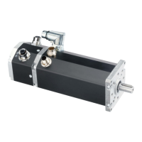
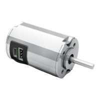
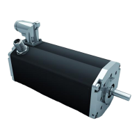
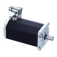
Describes the EC-motors (brushless DC) with integrated speed control for 4-quadrant operation.
Defines key technical terms and concepts used throughout the manual.
Specifies the intended industrial use and installation guidelines for the motor.
Lists relevant EU directives, machine, and EMC guidelines.
Emphasizes reading and observing safety instructions before operation.
Defines requirements for personnel handling and installing the drive.
Provides guidelines for safe storage and transport conditions.
Details electrical parameters like voltage, current, speed range, and power.
Covers mechanical data, dimensions, and environmental ratings.
Lists technical data for BG 75x25 SI, BG 75x50 SI, and BG 75x75 SI models.
Describes optional accessories like gears, brakes, and encoders.
Explains the ballast circuit for braking energy dissipation and protection.
Details the thermal shutdown mechanism to prevent overheating.
Describes the current monitoring and limitation to protect against overload.
Provides instructions for mounting the motor and shaft load limits.
Discusses EMC requirements and measures for industrial and residential use.
Explains the importance and method of connecting the ground wire.
Describes the standard 4-pole and 12-pole connector options for connectivity.
Details the 4-pin connector for motor power supply and pin assignments.
Explains the supply for the logic signals via the 12-pin connector.
Shows circuit diagrams for digital inputs and outputs.
Specifies maximum cable lengths for power and logic supply.
Warns about incorrect connections and polarity.
Illustrates the schematic circuit for power supply to the controller and motor.
Shows the wiring diagram for the motor's power supply connection.
Details the wiring diagram for the signal interface supply.
Guides on connecting voltage, control inputs, and initial power-up.
Explains the operating conditions triggered by digital inputs IN0 and IN1.
Details how digital inputs IN2 and IN3 control fixed speed settings.
Describes the procedure for teaching and storing fixed speed values.
Explains how to adjust and store acceleration and braking ramp times.
Describes the function and characteristics of the OUT1 pulse output.
Details protection functions and the fault signal via OUT2.
Explains how the analogue input controls motor speed.
Discusses the use of motors with an attached brake and required diode.
Covers maintenance requirements, removal from service, and proper disposal.
Provides contact information for support and troubleshooting.
Contains the CE declaration confirming product compliance.