2
Instruction Manual/Betriebsanleitung BG75SI, Version: 1.1 en_de
© 2011 Dunkermotoren GmbH; D-79848 Bonndorf; Germany
Page
1 Contents 2
2 About this document 4
3 General description 5
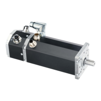
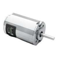
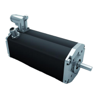
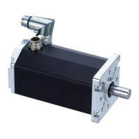
3.1 Motor series BG 75 SI 5
3.2 Explanations of terms used 6
3.3 Proper use 6
3.4 Standards and guidelines 7
4 Safety instructions 8
5 Technical data, accessories 9
5.1 Electrical data 9
5.2 Mechanical data 10
5.3 Dimensions 10
5.4 Motor BG 75x25 SI 11
5.5 Motor BG 75x50 SI 11
5.6 Motor BG 75x75 SI 11
5.7 Accessories 12
6 Protective functions 13
6.1 Ballast circuit 13
6.2 Over-temperature protection 13
6.3 Current limitation 13
7 Installation / terminal assignment 14
7.1 Mechanical assembly 14
7.2 Electromechanical compatibility 15
7.3 Ground wire 15
7.4 Connection alternatives 16
7.5 Motor power supply 16
7.6 Signal interface supply 17
7.7 Schematic circuit of the digital outputs 19
7.8 Schematic circuit of the digital inputs 20
7.9 Maximum cable length and
power supply 20
8 Connection schematic 21
8.1 Schematic circuit for power supply
controller/ motor BG75 SI 22
8.2 Connection motor power
supply 23
8.3 Connection signal interface supply 23
9 Operation hints 24
9.1 Operation 25
9.2 Function of the digital inputs
IN0 and IN1 25
Seite
1 Inhalt 2
2 Über dieses Dokument 4
3 Allgemeine Beschreibung 5
3.1 Motorbaureihe BG 75 SI 5
3.2 Begriserklärungen 6
3.3 Bestimmungsgemäße Verwendung 6
3.4 Normen und Richtlinien 7
4 Sicherheitshinweise 8
5 Technische Daten, Zubehör 9
5.1 Elektrische Daten 9
5.2 Mechanische Daten 10
5.3 Motormaßzeichnung 10
5.4 Motor BG 75x25 SI 11
5.5 Motor BG 75x50 SI 11
5.6 Motor BG 75x75 SI 11
5.7 Optionale Anbauten 12
6 Schutzfunktionen 13
6.1 Ballastschaltung 13
6.2 Übertemperaturschutz 13
6.3 Strombegrenzung 13
7 Installation und Anschlussbelegung 14
7.1 Mechanische Montage 14
7.2 Elektromagnetische Verträglichkeit 15
7.3 Schutzleiter Anschluss 15
7.4 Anschlussmöglichkeiten 16
7.5 Leistungsversorgung Motor 16
7.6 Schnittstellenversorgung 17
7.7 Prinzipschaltung der Digitaleingänge 19
7.8 Prinzipschaltung der Digitalausgänge 20
7.9 Maximale Kabellänge und
Spannungsversorgung 20
8 Anschlussschema 21
8.1 Prinzipschaltbild Spannungs
versorgung Regler/ Motor BG75 SI 22
8.2 Anschluss Leistungsversorgung
Motor 23
8.3 Anschluss Schnittstellenversorgung 23
9 Betriebshinweise 24
9.1 Inbetriebnahme 25
9.2 Funktion der Digitaleingänge
IN0 und IN1 25
 Loading...