122770 06 18-09-2007 53
ATC-140 A/B:
Remove the side panel by
unscrewing the 4 Allen screws and
the ground wire.
When remounting the ground wire
bee sure to replace the washers,
one on either side of the cable ring
tongues terminal.
Place the sensor (sensor kit
125152) in the hole at the bottom
of the well, together with 0.2ml
compound. The wires must point in
the same direction as on the
picture. The wires are secured to
the well with a wire holder. The
loose ends of the sensor are
connected to the reference sensor
connector pin 1 and 4. Remember
to short pin 1 and 2, and, 3 and 4.
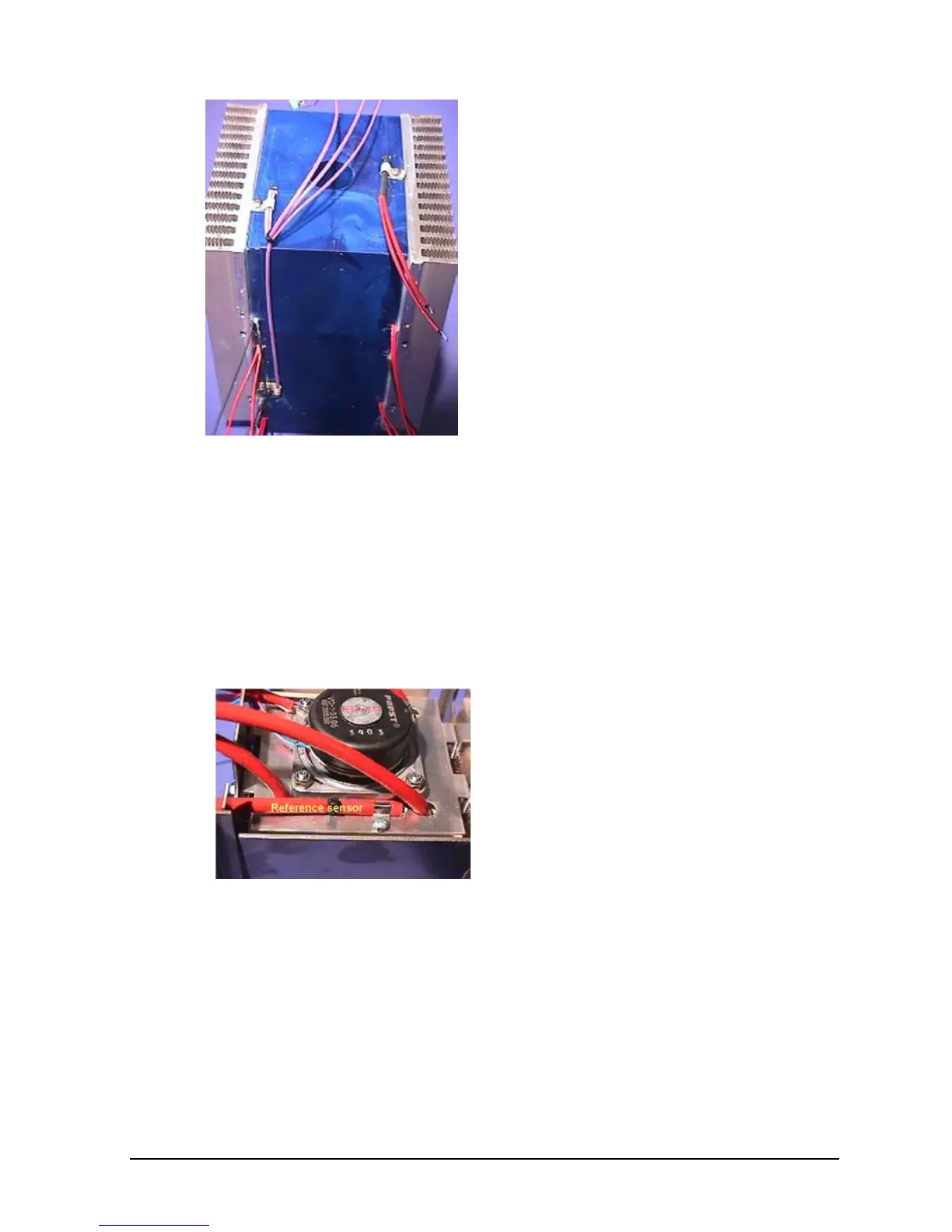
ATC-250 A/B:
Place the well unit upside down.
Unscrew the cable holder and
retract the reference sensor.
To reinstall a new reference
sensor, make sure that the hole is
free from foreign objects, install the
sensor and secure it with the cable
holder.

 Loading...


