122770 06 18-09-2007 59
2.3.1 DIP-Switch Settings
The difference between version 1 and version 2 is described as
follows:
PCB type Version 1 Version 2
Main PCB
Power PCB
4 pole DIP-Switch
None
5 pole DIP-Switch
8 pole DIP-Switch
Main PCB
Version 1 main board with version 1 power PCB.
When version 1 Main PCB’s (A and B model) are connected to
version 1 Power PCB’s, the DIP-Switch Settings on the Power PCB
are as follows:
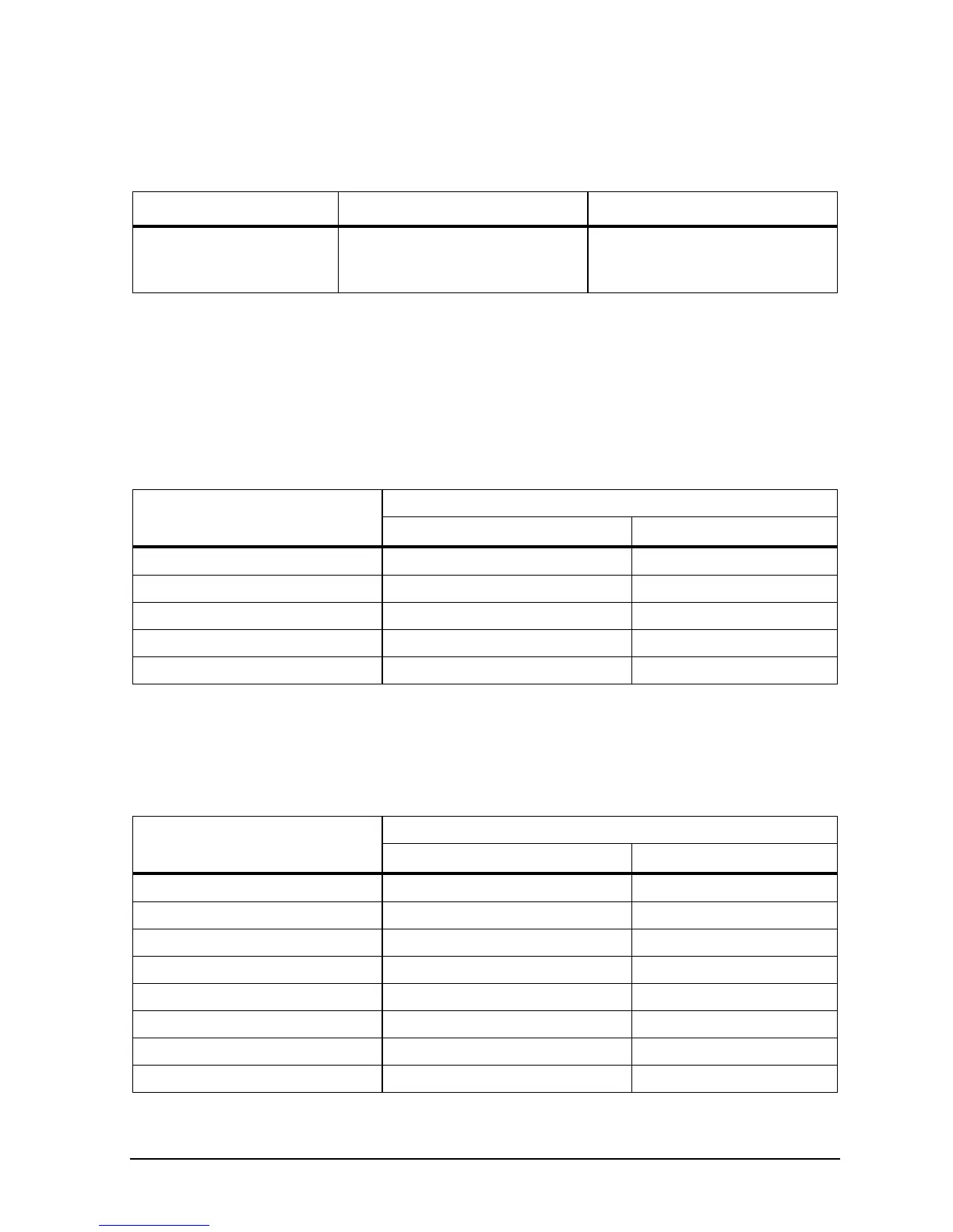
DIP-Switch Setting
Model
A model B model
ATC-155 0000 0001
ATC-156 1100 1101
ATC-157 0010 0011
ATC-320 1000 1001
ATC-650 0100 0101
DIP-Switch Settings on Version 2 Main PCB
Regardless which Power PCB is connected to version 2 Main PCB’s
(A and B model), the DIP-Switch Settings are as follows:
DIP-Switch Setting
Model
A model B model
ATC-125 10100 10110
ATC-140 01100 01110
ATC-155 00000 00010
ATC-156 11000 11010
ATC-157 00100 00110
ATC-250 11100 11110
ATC-320 10000 10010
ATC-650 01000 01010

 Loading...


