122770 06 18-09-2007 55
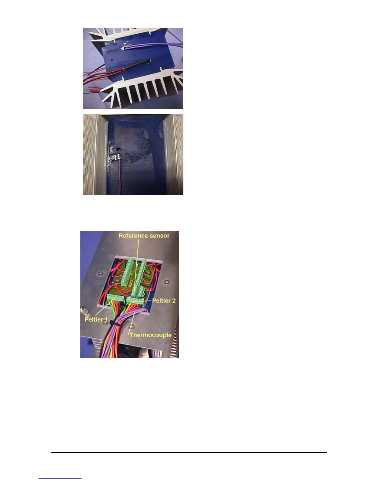
The thermocouple is the one
placed in the left hole from above
in the picture. Note that there are 2
wires to be retracted.
Remove the screw and the small
bracket attaching the thermo-
coupler to the well unit.
Retract the thermocouple from the
well unit.
When remounting the new sensor,
it must be placed in the two holes
together with 0.1ml compound.
ATC-140 A/B:
Remove the side panel by
unscrewing the 4 Allen screws and
the ground wire.
When remounting the ground wire
be sure to replace the washers,
one on either side of the Cable
Ring Tongue Terminal.
When installing the thermocouple
sensor (TC Kit 125170), the one
end with two wires, must be bend
90° 50mm from the tip of the wire.
The sensor is placed in the hole, in
the bottom of the well, together
with 0.3ml compound. The other
end is placed in the hole on the
side of well, together with 0.2ml
compound. Both ends of the
sensor are secured with a wire
holder.

 Loading...


