122770 06 18-09-2007 41
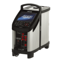
This picture shows an ATC-250 B.
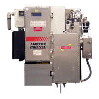
This picture shows an ATC-125 B.
D. Removal of Power PCB
(Exploded views, pos. 7).
ATC-140/155/156/157 A/B
Mark the 2 connectors to the Peltier
elements with a pen as shown on
the picture, before disconnecting
the connectors on the Power PCB.
The numbers correspond to the
text on the PCB.
When reassembling the connectors
be careful not to mistake the wire to
the FAN (red and black) with the
wires to the stirring motor (red and
blue).

 Loading...


