12
PARSTAT 2273 Hardware User’s Manual
NOTE
In
Electrochemistry PowerSuite
, when you connect or power on the PARSTAT 2273,
you must close the current experiment then use the software’s
Search for
Instruments
command or the
PowerSTAT
potentiostat control module to establish
communications with the PARSTAT 2273. See the
Electrochemistry PowerSuite
HTML Help Manual.
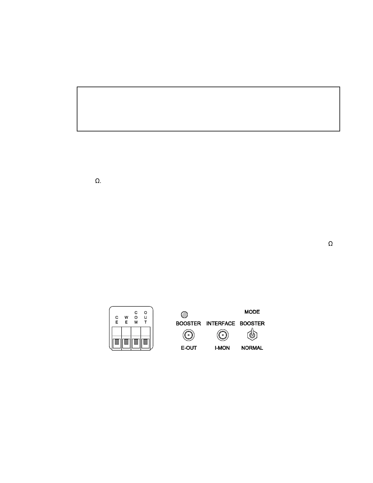
Fig. 5. Rear-Panel Power Booster Interface.
Interface. AUXILIARY INTERFACE can also turn the Model 616 Rotating Disk Electrode on and
off with the STIR signal issued within
Electrochemistry PowerSuite.
See Section 4.4 for the pin
assignments.
USB
— Attach the supplied USB cable (part no. 752860) to this connector and to the USB
connector on the PC. You can connect to and disconnect from the PC without shutting down or
restarting Windows or
Electrochemistry PowerSuite
.
SYNC ADC INPUT
— This BNC allows you to monitor an auxiliary signal in the ±10 V range with
16-bit resolution. This signal is monitored synchronously with the E and I channels.
NON-SYNC ADC INPUTS
Four nonsynchronous ADC inputs are provided. The input range is ±10 V with an input impedance
of 10 k
. These inputs allow you to monitor auxilliary signals with 12-bit resolution. Input signals
could include conditioned signals such as temperature, pH, pressure, or humidity. At this time, the
Electrochemistry PowerSuite software supports communication with these inputs only for EIS
(PowerSINE).
DAC OUTPUT — Rear-panel BNC delivers a precise dc voltage in the ±10 V range. This output
can be used to control the rotation speed of rotating disk electrodes (RDEs).
POWER AMPLIFIER MONITOR — Output of the power amplifier divided by ten. ±100 V range of
amplifier output gives ±10 V POWER AMPLIFIER MONITOR output. Output impedance is 50
.
3.2.1.2. Booster Interface
The rear-panel Booster Interface connectors and controls are shown in Fig. 5.
If a booster
interface is not installed, the holes will be unlabeled and covered with blanks.
CE — Terminal block accepts a 10 AWG wire from the counterelectrode.
WE — Terminal block accepts a 10 AWG wire from the working electrode.
COM — Terminal block accepts a 10 AWG ground-return wire from the Power Booster.
OUT — Terminal block accepts a 10 AWG output-voltage wire from the Power Booster.
E-OUT — Rear-panel BNC sends control signal telling the Power Booster what voltage to deliver.
 Loading...