15
Chapter 3 — INSTALLATION
WARNING
For operator and equipment safety, power to all instruments should be off
when connecting or disconnecting cables.
CAUTION
Take care that the leads
do not accidentally short together
. Because the
black ground lead is often unused, it tends to be overlooked. Because of
this, an accidental short involving this lead is usually more of a problem than
for the other leads.
3.3. Connecting to the PC and Cell
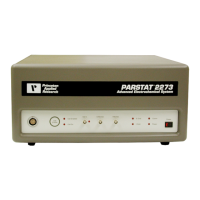
This section tells you how to connect the PARSTAT 2273 to the host PC and electrochemical cell,
and to other equipment you might wish to use with it.
3.3.1. Connecting to the PC
The PARSTAT 2273 is shipped with a standard USB cable. Connect it between the rear-panel
USB connector and a USB port on the PC. As noted above, you can connect to and disconnect
from the PC without shutting down or restarting Windows or
Electrochemistry PowerSuite
,
however, see the note in Section 3.2.1.1.
3.3.1.1. Installing the USB Driver
The first time the PARSTAT 2273 is connected to the host PC and powered on, Windows will
display a
Found New Hardware
message, then ask you to load the USB driver file,
ezusb.sys
.
To do this, insert the CD-ROM for your
Electrochemistry PowerSuite
module (supplied with the
instrument). On the Windows Taskbar, click on
Start
,
Run
. In the Run dialog, click on
Browse
,
then go to the CD-ROM. Double-click on the
\disk1
folder for any one of the
Electrochemistry
PowerSuite
modules (for instance,
PowerCORR
). Double-click on the
ezusb.sys
file, then click
on
OK
.
3.3.2. Connecting the Cell
To connect the cell cable (part no. 223622) to the PARSTAT 2273.
1. Make sure the POWER switch is off.
2. Grasp the connector on the cell cable by the grooved sleeve, turn it so the red dot aligns with
the red mark on the CELL connector, and press it into place. (To disconnect the cell cable
connector, grasp the grooved sleeve and pull straight out.)
3. Assemble the electrochemical test cell and prepare it with the test solution.
4. Connect the color-coded leads on the cell cable to the electrodes in the test cell as described
in the following steps.
5. In both potentiostatic and galvanostatic operation, connect the red lead to the counter
electrode and the green and gray leads to the working electrode. The reference electrode
plugs directly into the pin jack (white) and the black clip is ground. An accessory kit is
provided to convert the pin plugs to alligator clips, should you need them for your setup.
The polarity of the potential at the counter electrode will be opposite the “applied potential.”
This is necessary to establish the correct polarity relationship at the working electrode versus
the reference electrode.
Use of the black (ground) lead depends on a number of factors. In most cases it is not used,
although it is available if needed for a special purpose such as providing ground to a shield or
screen surrounding the cell.

 Loading...