14
PARSTAT 2273 Hardware User’s Manual
DANGER
Potentials as high as ±100 V at currents as high as 2 A could be present at the
counter electrode lead of the cell cable. The CELL ON indicator should always be
off
(unlit) when making the cell connections, as well as when the cable leads are
being examined or disconnected.
NOTE
The Cell Enable switch also acts as an emergency cell disconnect. During an
experiment, if you press Cell Enable while the cell is on, the cell will immediately be
disconnected and the experimented halted. The software will display an emergency
cell-disconnect warning.
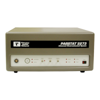
Ext In — ±10 V analog input. Potential applied is summed with that set within
Electrochemistry
PowerSuite
. Input impedance is 4.0 k
.
E Monitor — Front-panel analog output of voltage readings. Range ±10 V, 50
output
impedance.
I Monitor — Front-panel analog output of current readings. Range ±10 V, 50
output impedance,
0 to ±2 V corresponds to ±full-scale current range.
3.2.2.2. Controls
Power — On/off rocker switch.
Cell Enable —This safety override must be enabled (as indicated by the Cell Enabled LED)
before you can use an external cell; it does
not
turn on the cell. This does not affect the use of the
internal dummy cell. If you try to start an experiment without enabling the cell, the
Electro-
chemistry PowerSuite
software will prompt you to do so.
3.2.2.3. Indicators
Cell Enabled — This LED lights when the internal cell relay is closed. The cell relay is controlled
by the host PC.
Cell On — This LED lights when the internal cell relay is closed. The cell relay is controlled by the
host PC.
I Ovld (Current Overload) — The I Ovld LED lights if the working electrode current exceeds the
full-scale current range. This does not mean that the cell control loop is out of control. For
example, suppose the PARSTAT 2273 has been programmed to establish a potential of +0.752 V
and that under the established conditions a cell current of 0.5 mA occurs. If the current range is
2 µA, 20 µA, or 200 µA, the current-monitoring circuits will be driven to the limit and the I Ovld
indicator will light even though the cell is still controlled at +0.752 V.
E Ovld (Voltage Overload) — Unlike the I Ovld indicator, a lighted E Ovld indicator always
means that the cell control loop is
out of control
or the electrometer has exceeded the maximum
range of ±10 V. That is, the control amplifier has reached its maximum compliance voltage of
±100 V and the potential of the working electrode with respect to the reference electrode is not as
programmed. This could result from a connection error (open cell connection), an electrode
problem, an unacceptably high solution resistance, or an instrument problem.
Comm — This indicator lights when the PARSTAT 2273 and the computer are communicating.
Power — This indicator lights when the PARSTAT 2273 is powered on.

 Loading...