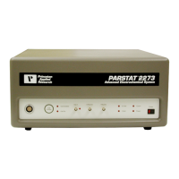
Do you have a question about the Ametek Princeton Applied Research PARSTAT 2273 and is the answer not in the manual?
| Model | PARSTAT 2273 |
|---|---|
| Type | Potentiostat/Galvanostat |
| Voltage Range | ±10 V |
| Current Range | ±2 A |
| Frequency Range | 10 µHz to 1 MHz |
| Input Impedance | > 10^12 Ω |
| Communication Interface | USB, Ethernet |
| Compliance Voltage | ±12 V |
| Maximum Current | ±2 A |
| Current Resolution | 30 fA |
| Voltage Resolution | 10 µV |
| Potential Range | ±10 V |
| Interface | USB, Ethernet |
| Data Acquisition | 16-bit |
Procedures for requesting and performing equipment service.
Guidelines for safely cleaning the instrument exterior.
Overview of various applications for the PARSTAT 2273.
Explains the connection and function of current booster options.
Details the host PC requirements and software compatibility.
Describes the internal circuitry for potentiostatic measurements.
Defines the positive and negative current conventions used.
Instructions for inspecting the instrument for shipping damage.
Information on instrument maintenance, service, and support resources.
Overview of the manual's chapter contents and structure.
Guidelines for safe connection of the power cord and grounding.
Instructions for selecting line voltage and replacing fuses.
Discusses conditions that might impair instrument safety or function.
Recommendations for system component placement and ventilation.
Specifies ventilation requirements for safe operating temperature.
Discusses minimizing RF interference from the instrument.
Explains susceptibility to various types of electrical transients.
Steps to ensure the PC's USB port is enabled for the instrument.
Details the various connectors and indicator lights on the instrument.
Description of connectors and controls on the rear panel.
Detailed description of the rear panel input and interface connectors.
Explains the rear-panel connectors for the booster interface.
Description of connectors and controls on the front panel.
Details the front panel connectors, including the cell cable.
Explains the function of the front panel controls like Power and Cell Enable.
Describes the meaning of the front panel indicator lights.
Instructions on connecting the instrument to the PC and test cell.
Steps for connecting the PARSTAT 2273 to the host PC via USB.
Guide for installing the necessary USB driver for PC communication.
Detailed steps for connecting the electrochemical test cell.
Detailed electrical specifications for the potentiostatic circuitry.
Specifications for the instrument's power amplifier section.
Specifications for the differential electrometer.
Details on the iR compensation features.
Specifications related to current measurement capabilities.
Specifications for potential and current control converters.
Specifies the frequency range for impedance measurements.
Covers physical dimensions, weight, and power requirements.
Specifies the environmental conditions for operation.
Lists the pin assignments for the auxiliary interface connector.