13
Chapter 3 — INSTALLATION
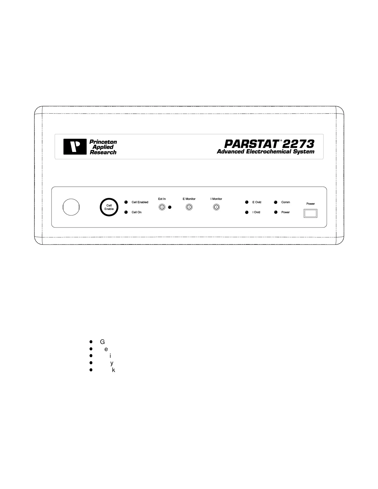
Fig. 6. PARSTAT 2273 Front Panel.
I-MON — Rear-panel BNC accepts signal indicating the current being provided by the Power
Booster.
NORMAL — Switches between BOOSTER mode and NORMAL (unboosted) mode. If you wish to
use the 2273 without the Power Booster, disconnect the cell cable from the Power Booster and
connect the standard 2273 cell cable to the 2273 front panel.
3.2.2. Front Panel
The PARSTAT 2273 front panel is shown in Fig. 6.
3.2.2.1. Connectors
CELL CABLE Connector and Cable — The cell cable (part no. 223622) connects to the 10-pin
CELL connector on the front panel via a LEMO-style connector. The connector is keyed so it can
only be inserted the correct way. To connect it, grasp it by the grooved sleeve, turn it so the red
dot aligns with the red mark on the CELL connector (this will ensure that the key aligns with the
keyway), and press it into place. To disconnect it, grasp the grooved sleeve and pull straight out.
At the other end of the cable are five color-coded leads. The color codes are:
Green: Working electrode lead
Red: Counter electrode lead
White: Reference electrode lead
Gray: Sense electrode lead
Black: Ground
In both potentiostatic and galvanostatic operation, the
RED
pin plug connects to the counter
electrode and the
GREEN
pin plug connects to the working electrode. The reference electrode
(
WHITE
) plugs directly into the pin-jack socket and the black clip is ground. The
GRAY
lead is the
sense lead and connects to the working electrode.
The use of the black lead depends on a number of factors. It is not ordinarily used with the
PARSTAT 2273, although it is available if needed for special purposes such as supplying ground
to a shield screen surrounding the cell.
 Loading...