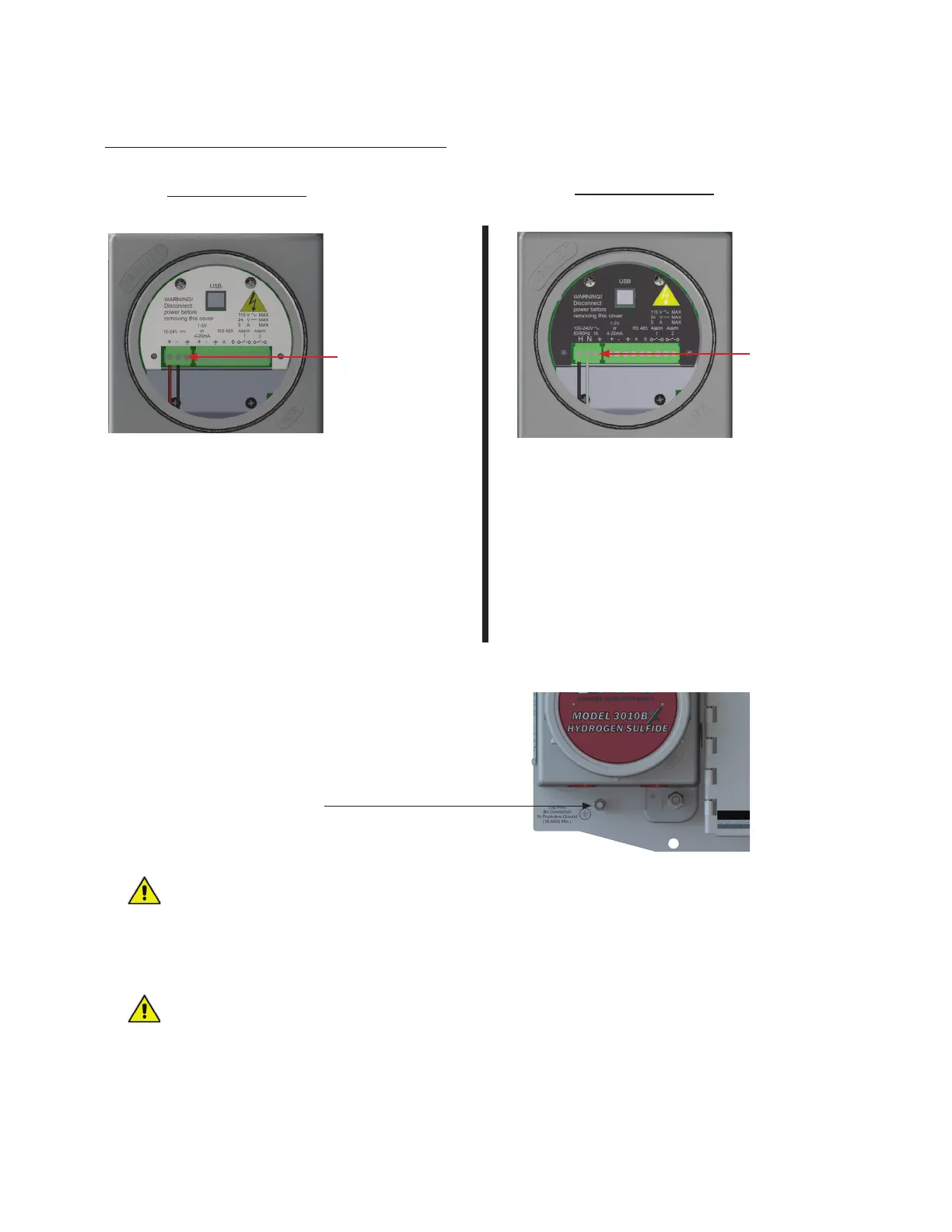
For DC Power:
7. Connect the DC power wires to the appropriate
terminals on the left.
• The + positive and - negative are clearly
marked on the sheet metal cover
• If you decide to use a 2-wire cable with shield for
the power supply connection, AMI provides
quality Shield Earth Ground Terminal Connection
next to the + positive and - negative terminals
For AC Power:
7. Connect the AC power wires to the appropriate
terminals on the left. The wire designations are
clearly marked on the black metal cover.
• H is for the Hot Wire
• N is for the Neutral Wire
• Position (A), as shown above, is for the AC Power
Ground
AC Power Ground
Terminal Connection (A)
Shield Earth Ground
Terminal Connection
(see recommendation
below)
1st CONDUIT (POWER & ALARMS):
Protective Ground
Lug
WARNING:
Analyzer must be connected to a Quality Protective Earth Ground for safety and the highest level of RFI
protection. This is accomplished by connecting an 16-gauge wire from the Analyzer's Protective Earth
Grounding Lug to an 8 foot ground rod or equivalent quality ground. (The Protective Grounding Lug is
located just below the explosion-proof housing as seen in the image above)
WARNING:
When using a AC power, never rely on the AC Power Ground as a source for Analyzer safety or ground
protection. Always connect the Protective Earth Ground Lug, shown above, to a high quality ground,
such as an 8 foot ground rod or equivalent.
12