EasyManua.ls Logo

AMI 1700 User Manual

AMI 1700
116 pages
To Next Page IconTo Next Page
Page #1 background imageLoading...
Page #1 background image
Revision 2; 3 August 2016
American Magnetics, Inc.
P.O. Box 2509, 112 Flint Road, Oak Ridge, TN 37831-2509, Tel: 865-482-1056, Fax: 865-482-5472
MODEL 1700
LIQUID LEVEL INSTRUMENT
(LIQUID NITROGEN VERSION)
INSTALLATION, OPERATION, AND
MAINTENANCE INSTRUCTIONS
EXCELLENCE IN MAGNETICS AND CRYOGENICS
1Cover Page

Table of Contents

Question and Answer IconNeed help?

Do you have a question about the AMI 1700 and is the answer not in the manual?

AMI 1700 Specifications

General IconGeneral
BrandAMI
Model1700
CategoryMeasuring Instruments
LanguageEnglish

Summary

General Precautions and Cryogen Safety

Cryogen Safety

Outlines safe handling precautions for cryogenic liquids like nitrogen and helium, including first aid for burns.

Safety Information and Warnings

Safety Legend and Warnings

Explains symbols used in the manual, defines warning and caution signs for hazards and product damage.

Equipment Warnings and Configuration

Equipment Warnings

Details critical warnings related to grounding, flammable gases, and equipment modification for safe operation.

Introduction to Model 1700 Instrument

Capacitance-Based Liquid Level Sensors

Explains the use of capacitance-based sensors for cryogenic liquids, noting requirements for insulated sensors and oscillator/transmitter units for longer distances.

Model 1700 Operational Capabilities

Model 1700 Panel Layouts

Front Panel Layout

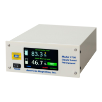
Illustrates and describes the layout of the Model 1700's front panel, including display and controls.

Rear Panel Layout and Description

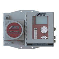
Illustrates and describes the rear panel, detailing connectors, ports, and a description table.

Model 1700 System Specifications

Installation Guide

Instrument Mounting and Sensor Installation

Guidance on mounting the instrument and installing capacitance sensors, emphasizing care to avoid damage.

Connecting the Capacitance Sensor

Setting Up the Autofill System

Autofill System Description

Explains the components of an autofill system: Model 1700, liquid level sensor, and solenoid valve.

Autofill System Setup Procedure

Power Requirements and Connections

Calibration Procedures

Capacitance-Based Level Calibration

Calibration Principles

Capacitance-based Sensor Calibration Methods

Selecting Calibration Methods

Pre-Calibration Procedure

Steps to enter sensor details like oscillator source and active length before calibration.

Loss of Sensor Calibration Procedure

Open Dewar Calibration Procedure

Approximate Calibration Method

Closed Dewar Calibration Procedure

Completing Closed Dewar Calibration

Remote Interface Reference

SCPI Command Set Reference

Setpoint Configuration Commands

Level Sensor Calibration Commands

System Control Commands

Error Codes Reference

Service and Repair

Battery Replacement Procedure

Fuse Replacement Procedure

Appendix: Troubleshooting and Licenses

Troubleshooting Assistance

Offers guidance for troubleshooting instrument problems and provides contact information for AMI Technical Support.

Related product manuals