Rev. 2 7
Introduction
Model 1700 System Specifications
1.4 Model 1700 Specifications @ 25°C
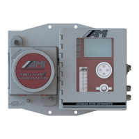
System Architecture
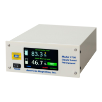
Display: 4.3” 24-bit color TFT display, 480x272 pixel
with resistive touch screen
Sensor types: Capacitance-based liquid level
Maximum length readout: Capacitance-based liquid level - 999 in
System operating firmware storage: Flash memory
System clock: Real time clock with automatic DST adjustment
Display measurement units: liquid level in cm, in or percent
Level Measurement
Resolution: 0.1%, 0.1 cm, 0.1 in
Accuracy: ±0.5% of active sensor length
Linearity: ±0.1% or 1 mm (whichever is greater)
Capacitance Sensor
Excitation Voltage:
5 V
DC
Capacitance Transmitter
Measurement Resolution:
0.7 pF
Operating Parameters
Alarm Set points: 0% to 100%, adjustable; Alarm condition settable
to above or below set point
Controller Output: Line voltage @ 2 A
AC
(maximum)
Sample and Hold Period: 1 second to 86,400 seconds (24 hrs)
Audible alarm: 3500 ± 500 Hz, 73 to 86 dB(A)
Analog Outputs
Output Types: 0-10 V
DC
and simultaneous 4 - 20 mA
DC
4-20 mA Current Loop
Power Supply Voltage:
12-32 V
DC
0-10 V
DC
Recorder Output
Output Load:
5k ohms or greater
Converter Resolution: 12 bits
Integral Non-linearity: ±1LSB
Differential Non-linearity
a
:
±1LSB
Relays
№1 and/or №2
(W171DIP-7, or equivalent):
Contact Form: 1 Form A (SPST-NO)
Maximum Switched Power: 0.29 W
Maximum Switched Current: 3 A
Switching Voltage: 60 V
AC
/ 100 V
DC
Auto Fill
Controller output socket: IEC 60320-13 socket on rear panel